


CT-3200 Installation Guide P. 3
order to avoid having to get out of the vehicle
and pressing the hood-pin switch. The PAB will
work only when the hood is up.
♦ inspect vehicle for any body damage or
electrical problems
♦ always solder and tape all connections.
♦ keep the transceiver away from other types of
antennas (GPS/Onstar).
♦ never install the control unit where it could
interfere with normal operation or obstruct
service technicians.
♦ always use a grommet when running wires
into the engine compartment. Never run wires
through bare or sharp metal.
♦ do not disconnect the battery on vehicles
equipped with air bags and anti-theft radios.
♦ never ground the control unit to the vehicle’s
steering column.
♦ make sure that all the switches and controls
operate properly.
♦ verify that the vehicle starts and idles
properly.
♦ make sure that all safety equipment is
installed: the valet button (if installed), the hood
switch and the warning label
♦ when wiring in parallel, make sure to isolate
each connection with a diode in order to avoid
feedback and possible damage.
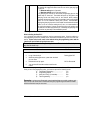
examples:
Wiring a clutch bypass and a transponder
module to the ground out when running
wire: at the junction point, where ground out
when running “splits” and goes to each device, a
diode is inserted on each of those lines.
Multiple or separate door pin connections:
When joining all door pins together to the door
pin input wire of the module, each wire must be
isolated with a diode to prevent feedback.
N.B.: the above examples reflect common
situations where diodes are use to isolate.
Please note that there are numerous other
scenarios where diode isolation is required.
♦ always make sure that any external relays or
modules added to the remote starter module are
properly fused, and diode isolated.
♦ when testing the shock sensor, never test on
glass with an opened hand, and never hit glass
hard enough as to break it. When testing on
metal or plastic, make sure the testing does not
result in damage to the vehicle (i.e.: dents,
broken glass, damaged trims, etc.).
♦ vehicles equipped with daytime running lights
may not allow the installer to view certain
programming results since the daytime running
lights do no go out (note: the parking light
output relay in the module gives two “clicks” per
flash, 1 click for on and 1 click for off).
♦ Parking light flashes referred to in this manual
refer to the parking light output of the module
and not that of the vehicle.
Harness Description
When connecting the module, it is important to make sure that the connector with the ground wire
is connected first, before making the 12-volt connections. Should the unit be powered up before
being grounded, there could be serious damage to internal components of the unit.
Be careful not to power up a module before it is properly grounded. To avoid any accident, it is
recommended to pull out the fuses from their sockets before the installation, and to put them back
during the very last steps.
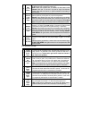
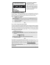
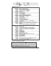
6-Pin Main Ignition Harness
Wire Description
A
RED
+12 V Battery
Connect to the largest 12 v supply wire at the ignition harness. Ensure that
the OEM power wire is fused for more than 30 a.
Note: certain new vehicles have no suitable 12 volts source at the ignition
switch (the 12 volt wire is too small to supply the necessary current). In this
case, the fuse box, or the b+ connection on the battery is recommended.
B
PURPLE
(+) 30 A
starter output
Connect to the starter wire of the vehicle (at the ignition switch). The source
wire should have +12 V with the Ignition key in the
CRANK position only.