


Installation Guide
WIRING CONNECTORS
5
WIRING CONNECTORS
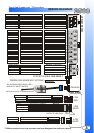
Yellow Starter 30amp output 12volts during crank only.
Green Heater 30amp output 12volts in accessory. Off during start.
Red 12 power 30amp input Constant 12volt power at ignition harness.
Red 12 power 30amp input Constant 12volt power at ignition harness.
Blue Ignition 1 30amp output 12volts in ignition and start positions.
White Selectable 30amp output Jumper Selectable. See Page 5.
Yellow Re-Arm 0.75sec Pulse With Lock And On Shutdown.
Orange (-) Output Negative While Locked -
**Starter Program Mode.
Brown Disarm 0.75sec Pulse With Unlock And Before Start.
Red/White 3rd CH Trunk Release - Active When The Unlock Button Is Held For 3seconds.
White/Violet (-)Running Negative Output While Running.
Green (-) Door Negative Door Trigger Input -
Manual Trans And Alarm Units Only.
Purple (+) Door Positive Door Trigger Input - Manual Trans And Alarm Units Only.
Green/White Hood Pin Negative Hood Pin Input - MUST BE CONNECTED!!
Pink Brake Positive Brake Input - MUST BE CONNECTED!!
Black Ground System Ground Input - MUST BE CONNECTED!!
Blue/White Tach Tach Signal Input - MUST BE CONNECTED!!
Blue Glow Plug Negative Glow Plug Input - DIESEL ENGINE ONLY. **Starter Program Mode.
White Park Lights Positive Park light Output - 10 Amp Max.
Black/White Park Brake Negative Park Brake Input - Manual Transmission Models Only.
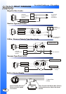
6 Pin Power Connector
14 Pin Connector
5
White/Green Channel 4 Programmable- See Alarm Settings. Menu 2.
Black Dome Light Negative Output For Dome Light Supervision.
White/Blue Siren Positive Output For Siren.
Red Trunk Pin Negative Input for Trunk Pin.
Green Door Lock Door Lock Output - Programmable - Menu 1 Setting 3.
Red 12 Volts Low Current Output. Use With Voltage Inverter
Blue Door Unlock Door Unlock Output - Programmable - Menu 1 Setting 3.
Pink 2nd Unlock Door Unlock Output - Programmable - Menu 1 Setting 3.
4 Pin Connector Square
4 Pin Connector Red
Jumper Selections
3 Pin Connector White
Green (-) Disarmed Negative Output When The System Is Disarmed.
Pink Horn/5th Channel Programmable Output.
Blue (+) Disconnect (+) Disconnect Or Instant Start Trigger.
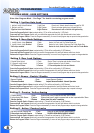
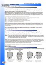
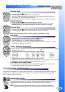
The jumpers control the output on the white wire from the
six pin harness. Place the jumpers in the above order to
change the output.
Note: The default setting is second ignition.
Output on White wire Jumper position
Second Starter Position 1
Second Accessory Position 2
Second Ignition Position 3
Back View Of Module
Jumpers
3 2 1