


Installation Guide
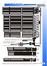
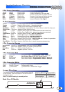
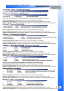
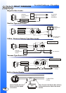
WIRING DIAGRAM
3
1
3
5
2
4
6
2
1
4
3
6
5
7
8
10
9
12
11
14
13
10
12
11
13
4 PIN BLUE
4 PIN
RED
4 PIN
WHITE
4 PIN
WHITE
4 PIN
WHITE
SIDE VIEW
SATELLITE LINK PLUG
STARTER DISABLE. SEE PAGE. 7
RF ANTENNA WITH DUAL LED’s
& BUILT-IN VALET SWITCH
***500ma outputs are low current and are designed to activate relays
*Must be connected to operate the system
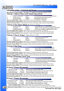
Blue
Green
Red
Red
Yellow
White / Green
White / Blue
BLK/WHT
BLK/WHT
Starter
Heater
Main Power
Ignition 1
Selectable P.5
Main Power
RE-ARM
STARTER DISABLE
FACTORY DISARM
TRUNK RELEASE
THIRD IGNITION (-)
(-) DOOR TRIGGER
HOOD PIN INPUT
(+) DOOR TRIGGER
BRAKE PEDAL
GROUND
TACH INPUT
GLOW PLUG
PARK LIGHTS
PARK BRAKE
4th Ch. Programmable
Siren Output
Dome Light Supervision
Trunk Pin Switch Input
YELLOW
WHITE / VIOLET
BLUE/WHT
BROWN
ORANGE
GREEN/WHITE
WHITE
BLUE
GREEN
BLACK/WHITE
PURPLE
PINK
BLACK
RED/WHITE
Black
Red
White
(+) 30amp Output
(+) 30amp Output
(+) 30amp Input
(+) 30amp Input
(+) 30amp Output
(+) 30amp Output
(-)500ma Output
(-)500ma Output
(-)500ma Output
(-)500ma Output
(-)500ma Output
(-)500ma Output
(-)500ma Output
Negative Input
Negative Input
Negative Input
Negative Input
Negative Input
(A/C) Input
(-) Input
Positive Input
Positive 15amp
Positive 3 amp
Positive Input
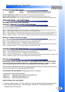
Green
Pink
Blue
Negative When Disarmed
Horn Honk/ 5th Channel
(-)500ma Output
(-)500ma Output
(+) Input
(+)Disconnect / Start trigger
Sensor Full-Warn
Sensor Pre-Warn
Sensor Ground
Sensor 12V+ Power
Black
Red
Blue
Green
(-)Input
(-) Input
(-)500ma Output
(+)500ma Output
Door Lock
12V+ for Relays
Door Unlock
Passenger Door Unlock
Red
Blue
Pink
Green
(-)500ma Output
(-)500ma Output
(-)500ma Output
(-)500ma Output
TEMPERATURE SENSOR INPUT (OPTIONAL)
Jumper Access