Lit. No. B64090, Rev. 00 13 April 1, 2006
MOLDBOARD & A-FRAME ASSEMBLY
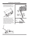
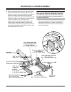
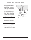
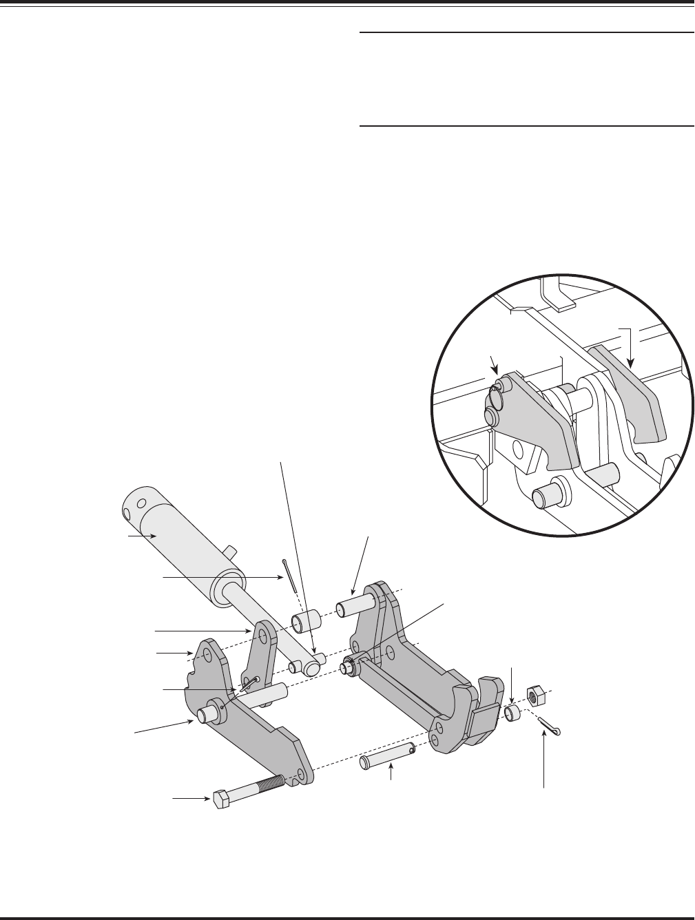
6. Remove the draw latch mount pin, spacer & cotter
pin from the draw latch assembly. By removing
this pin, the inner draw latch plates can swing free.
Remove the inner draw latch plate lift cylinder
mount pin. Position the plates on either side of the
lift/lower cylinder rod and insert the pin through the
plates and cylinder rod. With the cylinder
connected to the inner draw latch plates, rotate
the draw latch assembly toward the draw latch
mount holes on the A-frame. Align the holes in the
outer draw latch plate with those of the inner draw
latch plates and the A-frame.
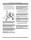
NOTE: The A-frame latch, located at the rear/center
of the A-frame, should be raised up to insert the
draw latch mount pin. Pull the A-frame latch pull
pin out and rotate the latch counterclockwise if it
is locked into position.
Secure the assembly to the A-frame by replacing
the draw latch mount pin, spacer and cotter pin.
Reset the A-frame latch so the A-frame latch pull
pin locks into place.
A-Frame
Latch Lock Pin
A-Frame
Latch
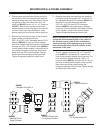
3/16" x 2-1/2"
Cotter Pin
Hydraulic
Lift/Lower Cylinder
Inner Draw Latch Plate
Lift Cylinder Mount Pin
3/4" x 2-1/2" or
5/8" x 2-3/8" (760LT only)
Draw Latch Mount Pin
1" x 4-21/32" or
1" x 3-7/8" (760LT only)
Draw Latch Arm Pivot Pin
3/4" x 2-1/2" or
3/4" x 2-3/8" for 760LT only
1" O.D. x 25/32" I.D. x 5/8"
Spacer
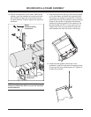
3/16" x 2-1/2"
Cotter Pin
1/4" x 1-1/2"
Cotter Pin
Draw Pin
1" x 6-1/2" or
1" x 5-5/8" for 760LT only
Clevis Pin
3/4" x 3-41/64" or
3/4" x 3-7/16" for 760LT only
Hex Head Cap Screw
3/4"-10 x 4-1/2" or
3/4"-10 x 4" for 760LT only
Inner Draw Latch Plate
Outer Draw Latch Plate


