Matrix Software, cont’d
MTPX Plus Twisted Pair Matrix Switchers • Matrix Software
5-26
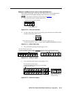
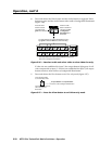
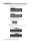
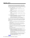
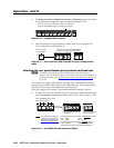
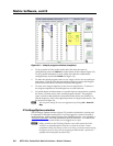
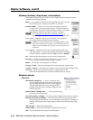
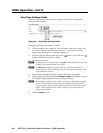
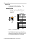
10. Tie the local input receiving the test pattern signal to the output to be
optimized.
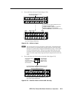
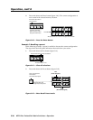
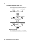
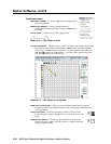
11. Use the test equipment or examine the displayed video image with a critical
eye to determine which video signal — red, green, or blue — is most shifted
to the left.
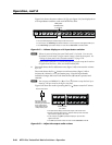
12. Adjust the leftmost video signal to the right until all three colors are
converged.
N
Whentheskewadjustmentissettozero,theMTPXPluscannotshiftthe
rightmost video image to the left.
N
A2-nanosecondadjustmentisveryne.Upto10nanosecondsofdelaymaybe
necessary before you detect a change in the display.
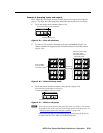
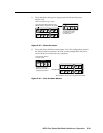
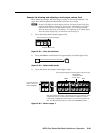
13. If either of the two the remaining colors is left shifted, repeat steps 11 and 12.
14. Repeat steps 9 through 13 for all other outputs.
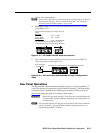
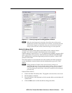
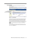
MTPX Plus Pre-Peak selection
N
MTPXPre-Peakisavailableontherst25%oftheMTPXPlusoutputs(for
example,outputs1through4foranMTPXPlus168).
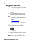
If the cable between the MTPX Plus and the receiver is > 300', turn the MTPX Plus’s
Pre-Peak feature on. For shorter cables, turn the feature off.
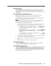
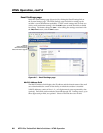
MTP Receiver level/peaking setting
If level/peaking is available on the connected receiver(s), adjust it as follows:
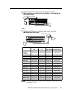
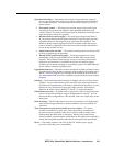
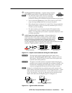
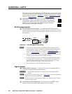
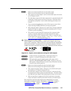
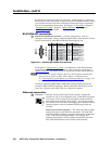
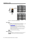
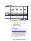
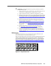
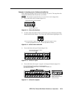
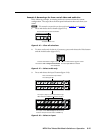
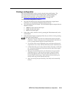
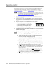
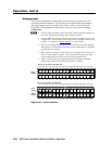
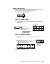
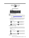
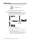
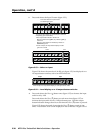
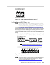
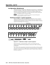
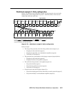
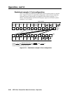
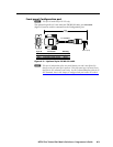
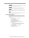
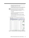
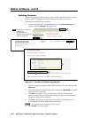
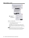
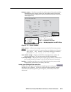
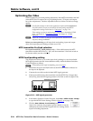
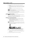
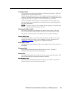
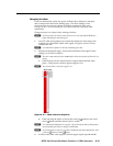
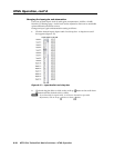
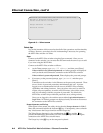
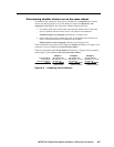
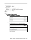
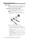
1. If using an oscilloscope, apply a white field test pattern to one the local
(VGA) inputs on the MTPX Plus (figure 5-21).
If using a monitor, apply a Color Bars test pattern to one the local (VGA)
inputs on the MTPX Plus.
H
TheExtronVTG300orVTG400arerecommendedtoprovidethetestpattern.
2. Tie the local input receiving the test pattern signal to the output connected to
the MTP receiver to be optimized.
MTP
receiver
VTG 300
Local (VGA)
input
MTPX Plus
INPUT
BUFFERED
OUTPUT
OUTPUT
POWER
12V
.5A MAX
MTP RL 15HD A
ON
1 2 3 4 5 6
H SYNC +
V SYNC +
C SYNC
SOG
VIDEO
END UNIT
1
MONO AUDIO
2
MONO AUDIO OUTPUTS
OUTPUTS
RGB
RGB
1
2
3
1
Tx Rx
1
L
R
12
AUDIO
3
2
L
R
3
L
R
4
L
R
LOCAL INPUTS
LOCAL OUTPUT
RGB
RGB
INPUT SELECT
ON
LOCAL
RJ - 45
123
RS-232/RS-422
REMOTE
CONTROL
RS - 232 OUTPUT INSERT
Tx Rx
Tx Rx
Tx Rx
Tx Rx
Tx Rx
Tx Rx
Tx Rx
INPUTS
12345 678
910111213141516
12345678
910111213141516
12345678
LAN
RESET
Oscilloscope
or display
RGB/R-Y,Y,B-YS-VIDEOCOMPOSITE
VIDEO
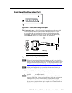
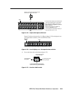
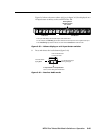
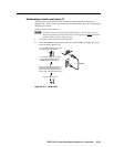
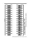
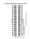
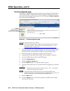
Figure 5-21 — Connections for setting the receiver’s level/peaking
3. Connect an oscilloscope or monitor to the output of the MTP receiver.
4. Adjust the receiver’s level/peaking in accordance with the applicable MTP
product manual.
5. Repeat steps 2 through 4 for each receiver to be optimized.