4-22
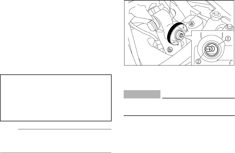
Adjust the compression damping force as fol-
lows.
1. Remove the seat. (See page 4-13 for
seat removal and installation proce-
dures.)
2. Turn the compression damping force ad-
justing screw in direction
a
to increase
the compression damping force and in di-
rection
b
to decrease the compression
damping force.
NOTE:
_
Make sure that the position indicator marks
are aligned when the shock absorber is set to
the standard setting.
_
1. Compression damping force adjusting screw
2. Position indicator marks
3. Install the seat.
CAUTION:
_
Never turn an adjusting mechanism be-
yond the minimum and maximum settings.
_
Minimum (soft): Adjusting screw fully turned
out
Standard: Adjusting screw 1/ 3/4 turns out
from the fully turned in position
Maximum (hard): Adjusting screw fully
turned in
U5TG10.book Page 22 Monday, April 7, 2003 8:50 PM


