


12 September 2006 V104 Manual
Tri-M Engineering Tel: 800.665.5600, 604.945.9565
1407 Kebet Way, Unit 100 Fax: 604.945.9566
Port Coquitlam, BC V3C 6L3 E-mail: info@tri-m.com
Canada Web site: www.tri-m.com
8
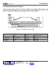
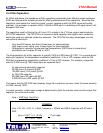
2.2 Power Considerations
The +5V switching regulator is rated at 5A maximum output however, the +5V output supplies power
to the +12, -5 and –12VDC regulators. The usable range of the +5V output can be calculated using
the following derating formula.
Usable +5VDC output = 5A-(I[-5] +I[12]*2.4) /0.80)
Where: I[-5] = -5VDC current load
I[-12] = -12VDC current load
I[12] = 12VDC current load
Assuming 80 percent converter efficiency (actual efficiency may vary).
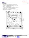
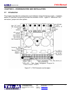
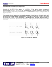
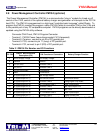
2.3.1 Main Input Power Connector
Input power is connected to the “pluggable” block, CN1, which is removable from the socket
connector on the circuit board. The power supply accepts DC input voltages in the range of 8VDC to
30VDC.
Unregulated vehicle power is connected as follows:
- Terminal 1: “hot” polarity
- Terminal 2: Common (0VDC)
!! CAUTION !!
To allow operation at the lowest possible input voltages (8VDC) and for the best efficiency, there is
NO input reverse-polarity diode provided on the V104 main DC input connector. If reverse-
polarity protection is required, connect to the AC input connector. See section 2.3.2
2.3.2 AC Input Power Connector (Optional)
Low voltage AC is connected to the V104 on screw terminal block, CN7. The V104 accepts AC
power in the range of 6VAC to 20VAC however, 12VAC to 16VAC is the recommended range. The
input capacitor on the V104 is 1000uF and is adequate for low power applications drawing one amp.
Connect an additional 1000uF capacitor to connector CN1 (terminal 1, positive, terminal 2 negative)
for greater loads.