


12 September 2006 V104 Manual
Tri-M Engineering Tel: 800.665.5600, 604.945.9565
1407 Kebet Way, Unit 100 Fax: 604.945.9566
Port Coquitlam, BC V3C 6L3 E-mail: info@tri-m.com
Canada Web site: www.tri-m.com
10
Example: NMH0515S (+15V) can generate the following voltages:
- +15V by connecting NMH “0V” to V104 common
- -30V by connecting NMH +V to common
- +30V by connecting NMH –V to common
- +42V by connecting NMH –V to +12V output
Note: When batteries or external signals are connected to CN3 the Plug-IN Boost regulator (VR3)
cannot be installed. See section 2.3.4
2.4 Bus Termination (Optional)
AC bus termination minimizes power consumption, while improving the reliability of the bus. The
resistor/ capacitor combination only conducts current during the few nanoseconds when the bus
signal is changing state.
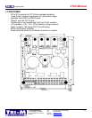
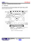
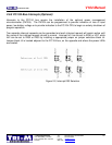
2.5 Installation onto PC/104
The PC/104 bus on the V104 is keyed according to the standards as set out be the PC/104
Consortium Guidelines. Male Pin B10 of the 8-bit bus and male pin C20 of the 16-bit bus are
removed but the female sockets are not “plugged”.
Because of the large number of pins and sockets (104 total) in the PC/104 bus, caution must be used
in separating the PC/104 modules to prevent bending the pins or hurting the person separating the
modules. Tri-M Engineering recommends the use of the PC/104 removal tool (model #5535),
available from Tri-M Engineering.
2.6.1 LED Jumper Enable/Disable
These jumpers allow the LEDs to be disabled. This is most likely to be used when absolute minimum
power consumption must be maintained, such as when operating off a limited battery source.
The location of each LED jumper is immediately behind each LED.
Each LED is enabled by factory default. To disable any LED, remove the LED jumper (or cut the
small PCB trace if no jumper is installed) associated with the LED. To re-enable any LED, re-install
the associated jumper (or solder a short jumper wire between each of the jumper pads).