


12 September 2006 V104 Manual
Tri-M Engineering Tel: 800.665.5600, 604.945.9565
1407 Kebet Way, Unit 100 Fax: 604.945.9566
Port Coquitlam, BC V3C 6L3 E-mail: info@tri-m.com
Canada Web site: www.tri-m.com
21
APPENDIX 4
BC104 Battery Charger and PM104 Power Management Units
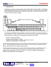
1) Description
When the BC104 and PM104 units are both installed on either the V104 (hereafter referred to as
PSU), a universal battery charger can be setup and the PSU unit made into an UPS
(uninterruptible power supply).
The BC104 is a constant current “buck” switching regulator with an adjustable “float” voltage. The
float voltage is adjusted via a potentiometer. The PM104 is programmed by the user using a
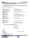
“control basic” called Pbasic. A sample program is supplied to show a typical NiCd charging
control. Before using the BC104 and the PM104 the battery charging program must be set up for
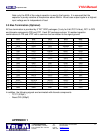
the intended battery pack. The sample program has separate settings for normal charge current
and trickle charge current. In addition, the charge termination methods should be set, including
maximum charge time, negative delta V. The user must set these for the type and size of battery
to be charged. Typically charge currents will be 1/3 to 1/6 of battery capacity and trickle charge
current 1/20 to 1/30 of battery capacity. Addition of a battery temperature sensor will allow charge
termination with elevated battery temperatures (which indicates battery is fully charged).
The PM104 can be programmed for many additional features not included in the sample program.
Features such as setting a PC/104 bus interrupt when main power fails, stopping the PSU after
running on battery backup power for a set time, tracking power consumption so that backup
battery charging can be terminated when the same amount is restored to the battery. These
features are left to the OEM integrate into their design.