


12 September 2006 V104 Manual
Tri-M Engineering Tel: 800.665.5600, 604.945.9565
1407 Kebet Way, Unit 100 Fax: 604.945.9566
Port Coquitlam, BC V3C 6L3 E-mail: info@tri-m.com
Canada Web site: www.tri-m.com
22
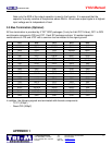
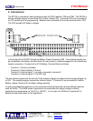
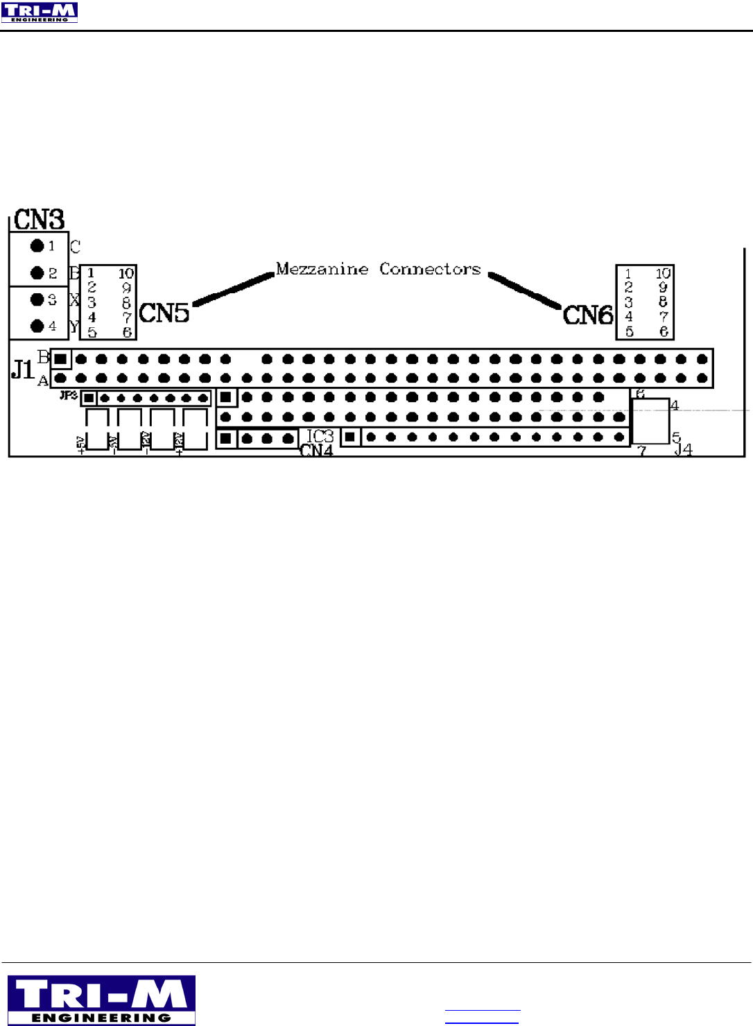
2. Connections:
The BC104 is mounted on two connectors under the PSU heatsink, CN5 and CN6. The PM104 is
factory installed directly in front of the PC/104 bus, location IC3. Connector CN4 is for connection
to a PC parallel port for programming. Batteries are connected to the screw terminal block, CN3.
The PSU accepts DC battery voltages
in the range of 8 to 20VDC through the Battery Power Connector CN3. Two external signals can
be connected to the battery terminal block for use by add-on modules plugged into the mezzanine
header connectors. Connect to the V104 Battery Terminal Block as follows:
- Terminal 1: Common of battery
- Terminal 2: Positive Battery Terminal
- Terminal 3: External signal 1, normally connected to terminal 2
- Terminal 4: External signal 2, 0 to 30V input
The two external signals are fed into the 12 bit analog to digital converter and will accept voltages up
to 30V. The sample program requires the External signal 1 (Terminal 3) be connected to Positive
Battery voltage (Terminal 2) for battery voltage sensing.
A variety of temperature sensors can be connected including thermistors and conditioned sensors
such as LM35s. The LM35 series is particularly nice because their output voltage is directly
proportional to temperature (ie 10mV/C or 10mV/F). In any case, the OEM can “experiment” to
determine what works best in their application.