


12 September 2006 V104 Manual
Tri-M Engineering Tel: 800.665.5600, 604.945.9565
1407 Kebet Way, Unit 100 Fax: 604.945.9566
Port Coquitlam, BC V3C 6L3 E-mail: info@tri-m.com
Canada Web site: www.tri-m.com
17
Note: only the ESR of the output capacitor is used in the formula. It is assumed that the
capacitor is purely resistive at frequencies above 20kHz. Worst case output ripple is at highest
input voltage and is independent of load.
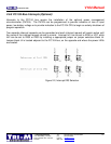
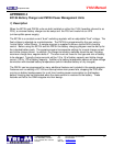
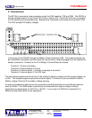
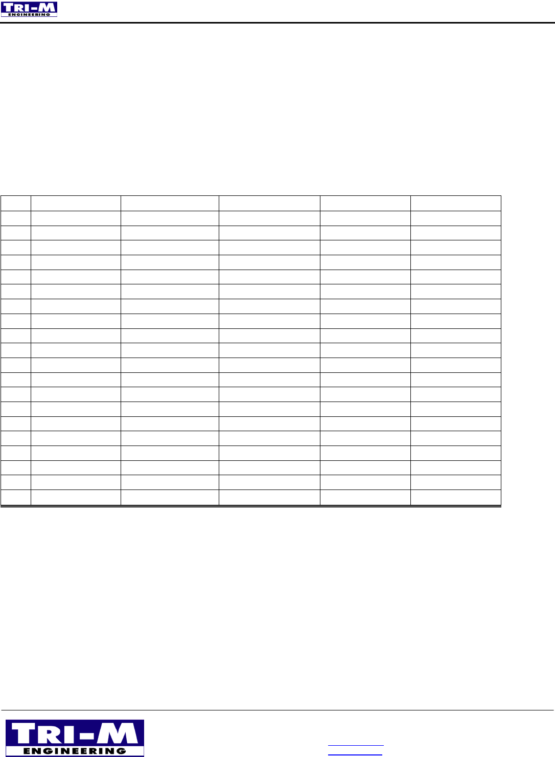
3.5 Bus Termination (Optional)
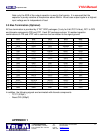
AC bus termination is provided by 5 “RC” SOIC packages (3 only for 8-bit PC/104 bus), RC1 to RC5
and discrete components C20 and C27. Each RC package contains 16 resistor/capacitor
combinations of 47R and 47PF with a common bus connected to the signal ground.
RC1 RC2 RC3 RC4 RC5
1
GND GND GND GND GND
2
*SMEMW IRQ10 *BACK6 SA11 SA3
3
AEN LA22 SD9 *Refresh BALE
4
IOCHRDY IRQ11 DRQ6 SA12 SA4
5
SD0 LA21 *DACK7 DRQ1 IRQ3
6
SD1 LA20 SD11 SA13 SA5
7
SRDY IRQ15 DRQ7 *DACK1 *DACK2
8
SD2 LA19 SD12 SA14 SA6
9
SD3 LA18 ---- SA15 SA7
10
GND GND GND GND GND
11
GND GND GND GND GND
12
SD7 *MEMR SD15 *IOW IRQ6
13
SD6 LA17 SD14 SA17 SA9
14
SD5 LA18 SD13 *IOR IRQ5
15
SD4 IRQ12 SD10 SA16 SA8
16
DRQ2 LA23 SD8 *DACK3 IRQ4
17
SA19 *IOCS16 DRQ5 DRQ3 DA2
18
*SMEMR *SBHE *MEMW IRQ7 SA1
19
SA18 *MEMCS16 *DACK5 SA10 SA0
20
GND GND GND GND GND
In addition, the following signals are terminated with discrete components.
- TC C1 (330pF)
- Reset C20 (330pF)
APPENDIX 1