


12 September 2006 V104 Manual
Tri-M Engineering Tel: 800.665.5600, 604.945.9565
1407 Kebet Way, Unit 100 Fax: 604.945.9566
Port Coquitlam, BC V3C 6L3 E-mail: info@tri-m.com
Canada Web site: www.tri-m.com
15
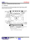
CHAPTER 3 – THEORY OF OPERATION
3.1 Input power protection:
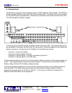
Input power is connected to the screw terminal block, CN1, which is removable from the socket
connector on the circuit board. A seven ampere ‘pico’ fuse F1 limits the current draw from the power
source. A series of devices, (toroid coil L3, transorb D4 and filter capacitor C12) filters and clamps
the input power.
Transorb D4 is a 5KVA, heavy duty transient suppressor that provides “zener” type protection and
has an avalanche voltage of 33V. It is electrically located before fuse F1 to prevent activation of the
fuse during a “load dump” or large transient. Sustained voltages greater than the avalanche voltage
must not be applied or transorb D4 will fail.
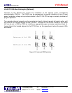
3.2 Switching regulator, +5VDC
A simple switcher regulator VR1, generates the +5VDC output, operating in a “buck” mode switching
regulator configuration using inductor coil L1, schottky diode Z1, input filter capacitors C12 and output
filters capacitor C6. Regulator VR1 is a current mode controller and adjusts the “switching cycle” by
the sensed current rather than directly by the output voltage. Control of the output voltage is obtained
by using the output of a voltage sensing error amplifier in regulator VR1 to set the current trip level.
A total of 5 amperes can be supplied to the connected +5VDC load, to the inputs of the +12VDC
regulator and the –5VDC and –12VDC charge pumps and invertors. The +5VDC power is available
on the PC/104 expansion bus (B3, B29 and D16) and screw terminal connector CN2. LED2 provides
indication of +5V operation.
3.3 Switching regulator, +12VDC
Switching regulator VR2 generates the +12VDC output, operating in a “boost” mode switching
regulator configuration using inductor coil L2, Schottky diode D11, input filter capacitor C6 and output
filters capacitor C3. Capacitor C6 works as an output filter for the +5VDC and as an input filter for the
+12VDC regulator VR2. Regulator VR2 is a current mode controller and adjusts the “switching cycle”
by the sensed current rather than directly by the output voltage. Control of the output voltage, sensed
by resistors R5 and R6, is obtained by using the output of a voltage sensing error amplifier in
regulator VR2 to set the current trip level. If a custom output voltage is ordered, variable resistor R21
(in series with R5) will adjust the feedback voltage.
A total of one ampere can be supplied to the connected +12VDC load and the –12VDC inverter. The
+12VDC power is available on the PC/104 expansion bus (B9) and screw terminal connector CN2.
LED1 provides indication of +12VDC operation.