


12 September 2006 V104 Manual
Tri-M Engineering Tel: 800.665.5600, 604.945.9565
1407 Kebet Way, Unit 100 Fax: 604.945.9566
Port Coquitlam, BC V3C 6L3 E-mail: info@tri-m.com
Canada Web site: www.tri-m.com
16
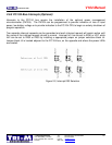
3.4 Filter Capacitors
At 10kHz and above, the impedance of filter capacitors is essentially their effective series resistance
(ESR) and this parasitic resistance limits the filtering effectiveness of the capacitors. Since the filter
capacitors must absorb the “switching ripple” current, capacitors with high ESR values will quickly
overheat. For example, a capacitor with a 100mOhm ESR which is absorbing a 5A ripple current, will
dissipate 2.5W heat.
The capacitors used for filtering the +5V and +12V outputs in the V104 are organic semiconductor
(OS-CON) capacitors. The OS-CON is an aluminium solid capacitor with organic semi-conductive
electrolyte used as a cathode conductive materials. The OS-CON has many advantages over the
conventional electrolytic:
- Very low ESR values, less than 8 times lower for same package.
- High ripple current rating, over 4 times higher for same package.
- No degrade in operation at extended low temperatures. (ESR value of conventional
electrolytics can increase 25 fold at –40C).
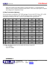
The life expectation for a filter capacitor is typically 2,000 to 6,000 hours @ 105C. For a conventional
electrolytic capacitor the temperature acceleration coefficient = 2 for a 10C increase, while the OS-
CON has a temperature acceleration coefficient =10 for a 20C increase. For example, a capacitor
rated for 2,000 hours @ 105C would have an expected life of:
- for conventional electrolytic capacitor
32,000 hours (3.6 years) @ 65C
128,000 hours (14.6 years) @ 45C
- for OS-CON capacitor
200,000 hours (22 years) @ 65C
2,000,000 hours (220 years) @ 45C
This means that the OS-CON has extremely longer life in practical use even under the same warranty
of 2,000 hours @ 105C.
In a buck convertor, output ripple voltage is determined by both the inductor value and the output filter
capacitor (for continuous mode).
Vp-p = ESR*Vout (Vout/Vin))
L1 * frequency
EXAMPLE
Vout = 5V, Vin = 16V, L1 = 55uH, frequency = 100kHz and 330uF capacitor with 27mohm
ESR.
Vp-p = 0.027 * 5 (1- (2/16))
~ 17mV ripple
55 * 10E-6 * 10E5