


2005 CAMRY (EWD586U)
95
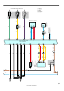
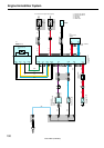
2. Control System
∗ SFI system
The SFI system monitors the engine condition through the signals input from each sensor to the engine control module.
And the control signal is output to TERMINALS #10, #20, #30, #40 of the engine control module to operate the injector
(Inject the fuel). The SFI system controls the fuel injection operation by the engine control module in response to the
driving conditions.
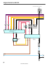
∗ ESA system
The ESA system monitors the engine condition through the signals input to the engine control module from each sensor.
The best ignition timing is decided according to this data and the memorized data in the engine control module and the
control signal is output to TERMINALS IGT1, IGT2, IGT3, IGT4. This signal controls the igniter to provide the best
ignition timing for the driving conditions.
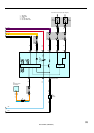
∗ Heated oxygen sensor heater control system
The heated oxygen sensor heater control system turns the heater on when the intake air volume is low (Temp. of
exhaust emissions is low), and warms up the heated oxygen sensor to improve detection performance of the sensor.
The engine control module evaluates the signals from each sensor, and outputs current to TERMINALS HT1B and
HT1C (California) to control the heater.
3. Diagnosis System
With the diagnosis system, when there is a malfunction in the engine control module signal system, the malfunctioning
system is recorded in the memory. The malfunctioning system can be found by reading the code displayed by the
malfunction indicator lamp.
4. Fail–Safe System
When a malfunction has occurred in any system, if there is a possibility of engine trouble being caused by continued control
based on the signals from that system, the fail–safe system either controls the system by using data (Standard values)
recorded in the engine control module memory or else stops the engine.