


2005 CAMRY (EWD586U)
82
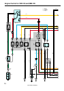
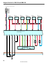
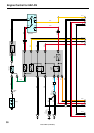
Engine Control for 1MZ–FE and 3MZ–FE
2. Control System
∗ SFI system
The SFI system monitors the engine condition through the signals, which are input from each sensor to engine control
module. The best fuel injection volume is decided based on this data and the program memorized by the engine control
module, and the control signal is output to TERMINALS #10, #20, #30, #40, #50 and #60 of the engine control module
to operate the injector (Inject the fuel). The SFI system produces control of fuel injection operation by the engine control
module in response to the driving conditions.
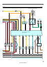
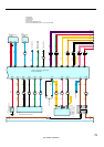
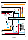
∗ ESA system
The ESA system monitors the engine condition through the signals, which are input to the engine control module from
each sensor. The best ignition timing is decided according to this data and the memorized data in the engine control
module, and the control signal is output to TERMINALS IGT1, IGT2, IGT3, IGT4, IGT5 and IGT6. This signal controls
the igniter to provide the best ignition timing for the driving conditions.
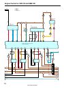
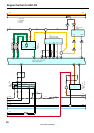
∗ Heated oxygen sensor heater control system
The heated oxygen sensor heater control system turns the heater on when the intake air volume is low (Temp. of
exhaust emissions is low), and warms up the heated oxygen sensor to improve detection performance of the sensor.
The engine control module evaluates the signals from each sensor, current is output to TERMINALS HT1B and HT2B,
controlling the heater.
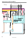
∗ Air fuel ratio sensor heater control system
The air fuel ratio sensor heater control system turns the heater on when the intake air volume is low (Temp. of exhaust
emission is low), and warms up the air fuel ratio sensor to improve detection performance of the sensor.
The engine control module evaluates the signals from each sensor, current is output to TERMINALS HA1A and HA2A,
controlling the heater.
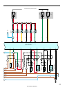
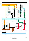
∗ ACIS
ACIS includes a valve in the bulkhead separating the surge tank into two parts. This valve is opened and closed in
accordance with the driving conditions to control the intake manifold length in two stages for increased engine output in
all ranges from low to high speeds.
The engine control module judges the engine speed by the signals from each sensor and outputs current to the
TERMINAL ACIS to control the VSV (ACIS No.1).
3. Diagnosis System
With the diagnosis system, when there is a malfunction in the engine control module signal system, the malfunctioning
system is recorded in the memory.
4. Fail–Safe System
When a malfunction occurs in any systems, if there is a possibility of engine trouble being caused by continued control
based on the signals from that system, the fail–safe system either controls the system by using data (Standard values)
recorded in the engine control module memory or else stops the engine.