


2005 CAMRY (EWD586U)
131
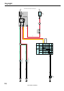
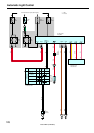
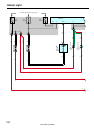
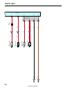
1. Normal Lighting Operation
<Turn taillight on>
With the light control SW turned to TAIL position, a signal is input into TERMINAL (A) 8 of the body ECU. Due to this signal,
the current flowing to TERMINAL 14 of the ECU flows to TERMINAL (A) 8 to TERMINAL 14 of the light control SW to
TERMINAL 16 to GROUND, and TAIL relay causes taillights to turn on.
<Turn headlight on>
With the light control SW turned to HEAD position, a signal is input into TERMINALS (A) 8 and (A) 9 of the body ECU. Due to
this signal, the current flowing to TERMINAL 15 of the ECU flows to TERMINAL (A) 9 to TERMINAL 13 of the light control
SW to TERMINAL 16 to GROUND in the headlight circuit, and causes taillight and HEAD relay to turn the lights on. The
taillight circuit is same as above.
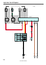
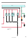
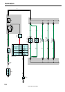
2. Light Auto Turn Off Operation
With light on and ignition SW turned off (Input signal goes to TERMINAL 9 of the ECU), when the driver’s door is opened
(Input signal goes to TERMINAL (C) 1 of the ECU), the body ECU operates and the current is cut off which flows from
TERMINAL 14 of the ECU to TERMINAL (A) 8 In taillight circuit and from TERMINAL 15 to TERMINAL (A) 9 in headlight
circuit.
As a result, all lights are turned off automatically.
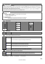
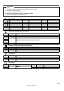
TAIL Relay
5–3 : Closed with the light control SW at HEAD or TAIL position
HEAD Relay
5–3 : Closed with the light control SW at HEAD position or dimmer SW at FLASH position
Closed with the engine running and parking brake released (Parking brake SW off)
Body ECU
9–Ground : Approx. 12 volts with the ignition SW at ON or ST position
12, 24–Ground : Always continuity
1–Ground : Always approx. 12 volts
D6 Door Courtesy SW Front LH
1–Ground : Closed with the driver door open
: Parts Location
Code See Page Code See Page Code See Page
B6 A 40 C11 40 J4 41
B8 C 40 D6 42 J23 41
:
Relay Blocks
Code See Page Relay Blocks (Relay Block Location)
1 22 Engine Room R/B (Engine Compartment Left)
:
Junction Block and Wire Harness Connector
Code See Page Junction Block and Wire Harness (Connector Location)
1H 25 Engine Room Main Wire and Engine Room J/B (Engine Compartment Left)
2B 28 Instrument Panel Wire and Driver Side J/B (Lower Finish Panel)
2E
28
Engine Room Main Wire and Driver Side J/B (Lower Finish Panel)
2F
28 Engine Room Main Wire and Driver Side J/B (Lower Finish Panel)
2R 29 Instrument Panel Wire and Driver Side J/B (Lower Finish Panel)
:
Connector Joining Wire Harness and Wire Harness
Code See Page Joining Wire Harness and Wire Harness (Connector Location)
IC2 50 Instrument Panel Wire and Floor Wire (Left Kick Panel)
System Outline
Service Hints