


2005 CAMRY (EWD586U)
94
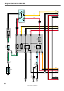
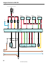
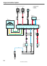
Engine Control for 2AZ–FE
The engine control system utilizes a microcomputer and maintains overall control of the engine, transaxle etc. An outline of
the engine control is given here.
1. Input Signals
(1) Engine coolant temp. signal circuit
The engine coolant temp. sensor detects the engine coolant temp. and has a built–in thermistor with a resistance, which
varies according to the engine coolant temp.. The engine coolant temp. which is input into TERMINAL THW of the
engine control module as a control signal.
(2) Intake air temp. signal circuit
The intake air temp. sensor is installed in the mass air flow meter and detects the intake air temp. which is input as a
control signal to TERMINAL THA of the engine control module.
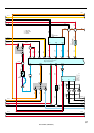
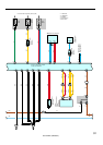
(3) Oxygen density signal circuit
The oxygen density in the exhaust emission is detected by the heated oxygen sensor and input as a control signal to
TERMINALS OX1B and OX1C of the engine control module (HT1B and HT1C)
(4) RPM signal circuit
Camshaft position and crankshaft position are detected by the camshaft position sensor and crankshaft position sensor.
Camshaft position is input as a control signal to TERMINAL G2+ of the engine control module, and engine RPM is input
into TERMINAL NE+.
(5) Throttle position signal circuit
The throttle position sensor detects the throttle valve opening angle as a control signal, which is input into TERMINALS
VTA1 and VTA2 of the engine control module.
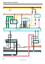
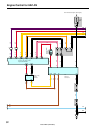
(6) Vehicle speed circuit
The vehicle speed sensor, detects the vehicle speed and input to ABS speed sensor of the skid control ECU with
actuator, from skid control ECU with actuator to TERMINAL SPD of the engine control module, Via combination meter.
(7) Battery signal circuit
Voltage is constantly applied to TERMINAL BATT of the engine control module. With the ignition SW turned on, the
voltage for engine control module start–up power supply is applied to TERMINALS +B and +B2 of the engine control
module via the EFI relay.
(8) A/C SW signal circuit
The A/C control assembly (Automatic A/C) or A/C amplifier (Manual A/C) inputs the A/C operations into TERMINAL AC1
of the engine control module.
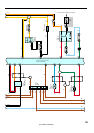
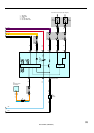
(9) Stop light SW signal circuit
The stop light SW is used to detect whether the vehicle is braking or not and the signal is input into TERMINAL STP of
the engine control module as a control signal.
(10)Starter signal circuit
To confirm whether the engine is cranking, the voltage is applied to the starter motor during cranking is detected and the
signal is input into TERMINAL STA of the engine control module as a control signal.
(11) Engine knock signal circuit
Engine knocking is detected by knock sensor and the signal is input into TERMINAL KNK1 as a control signal.
(12)Air fuel ratio signal system
The air fuel ratio is detected and input as a control signal into TERMINAL AF1A+ of the engine control module.
System Outline