


2005 CAMRY (EWD586U)
9
B
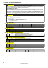
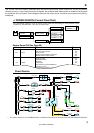
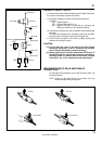
The ”Current Flow Chart” section, describes which parts each power source (fuses, fusible links, and circuit breakers)
transmits current to. In the Power Source circuit diagram, the conditions when battery power is supplied to each system
are explained. Since all System Circuit diagrams start from the power source, the power source system must be fully
understood.
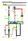
ACC
S 2
6
65
2
2
2
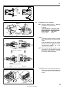
Battery
30A AM2
Starter
Short Pin
100A ALT
Fusible Link Block
60A ABS
10A ECU–B
7.5A DOME
15A EFI
10A HAZARD
20A RADIO NO.1
10A HORN
20A
10A
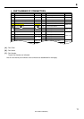
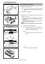
Fuse Page
214
230
112
122
194
187
180
166
210
ABS
Cigarette Lighter
Combination Meter
Key Reminder and Seat Belt Warning
Light Auto Turn Off
Theft Deterrent and Door Lock Control
ABS and Traction Control
Cruise Control
Electronically Controlled Transmission
Multiplex Communication System
STOP
System
DOME
Headlight
Interior Light
3 EA2 1 EA1
E 6
E 7
E 7
2
2
2
2
2
2
2
2
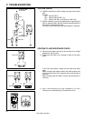
INJECTION Relay
STARTER Relay
B
B
B
B–O
1
1
2
2
3
4
3
4
W–B
W–B
B–W
B–W
E 7
E 7
B
B
W
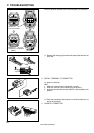
1.25B FL MAIN
50A MAIN
7.5A AM2
15A HAZ–RADIO
2
2
2
2
2
W
W
EB1
EB1
7
6
W–R
I 2 I 2
I 2
WW
W
W
W
1
1
1
1
40A DOOR LOCK CB
7.5A DOME
1
W–L
R
1
1
2
43
1
11
1
11
1
G
G
W–R
15A TAIL
20A DEFOG
B–Y
84
32
Ignition SW
I 8
B–Y
11
P–L
Battery
15A RAD CIG
2
TAIL
Relay
Power Source
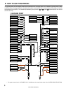
J POWER SOURCE (Current Flow Chart)
Engine Room R/B (See Page 20)
2
W
W
BBBBB
W–R
WWW
G–W
AM2
AM1
IG2
IG1
W
W
The chart below shows the route by which current flows from the battery to each electrical source
(Fusible Link, Circuit Breaker, Fuse, etc.) and other parts.
∗ The system shown here is an EXAMPLE ONLY. It is different to the actual circuit shown in the SYSTEM CIRCUITS SECTION.