


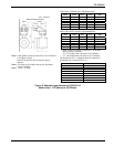
TIC-LF414C
9
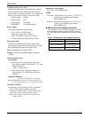
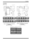
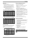
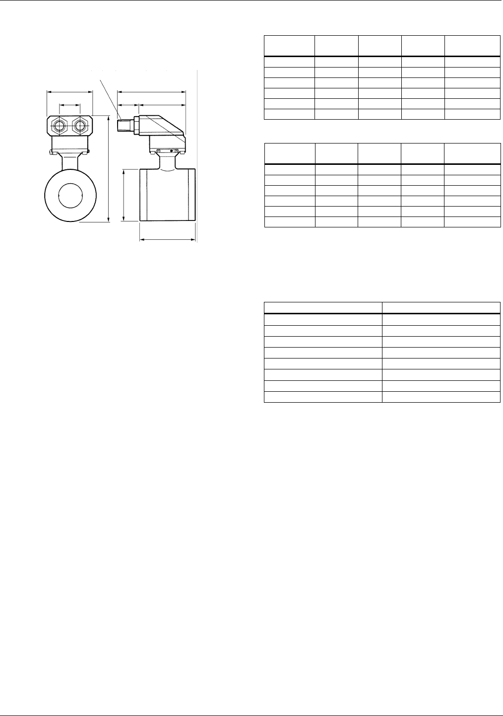
Unit : inch(mm)
3.46(88)
1
.57
(
4
0
)
4.96(126)
1. 38 ( 3 5 )
3.58(91)
R(PT)½Male Screw (Two places)
(L2)
L1
Φ
D1
Note1: Cable glands are not provided for LF414 of FM and
CSA approved type.
Refer to the part of Cable connection port at
detector.
Note2: Eye bolts are provided at the top for flowmeters
sized 8"(200mm).
Note3: 1 inch = 25.4mm
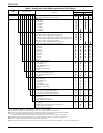
ANSI class 150 and class 300 dimensions:
Meter size
(inch)
L1
(inch)
L2
(inch)
D1
(inch)
Weight
(lbs)
1-1/2 3.94 7.48 3.35 approx. 9
2 4.33 8.15 4.02 approx. 11
3 4.33* 9.13 5.00 approx. 13
4 4.72* 10.39 6.26 approx. 20
6 9.06 12.76 8.50 approx. 47
8 11.81 15.16 10.51 approx. 78
BS16, DIN PN16 and JIS 10K dimensions:
Meter size
(mm)
L1
(mm)
L2
(mm)
D1
(mm)
Weight
(kg)
40 100 190 85 approx. 4
50 110 207 102 approx. 5
80 110* 232 127 approx. 6
100 120* 264 159 approx. 9
150 230 324 216 approx. 21
200 300 385 267 approx. 35
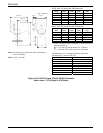
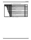
* When Teflon PFA lining is selected, L1 in the table
above becomes as follows:
L1: 4.53 inch(115mm) for meter size 3"(80mm)
L1: 4.96 inch(126mm) for meter size 4"(100mm)
The dimension of L1 is changed when the material of
grounding ring is chosen Pt-Ir or Ta
Meter size L1
1/2”(15mm) 3.03 inch(77mm)
1”(25mm) 3.74 inch(95mm)
1 1/2”(40mm) 4.53 inch(115mm)
2”(50mm) 4.96 inch(126mm)
3”(80mm) 4.96 inch(126mm)
4”(100mm) 5.35 inch(136mm)
6”(150mm) 9.53 inch(242mm)
8”(200mm) 12.28 inch(312mm)
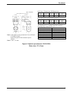
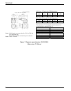
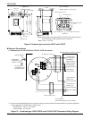
Figure 8. Separate type detectors LF410/LF414
Meter sizes 1 1/2"(40mm) to 8"(200mm)