


TIC-LF414C
13
Meter Size
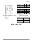
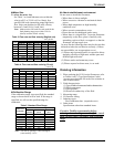
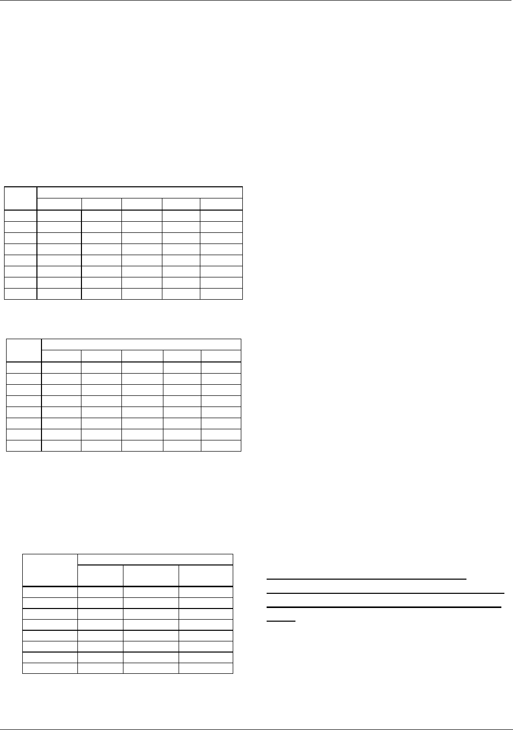
To select the meter size:
See Table 3 to 4 and find
meter sizes within the
velocity of 0.3 to 32.8 ft/s (0.1 to 10m/s) for a
specified full-scale (measuring range high limit)
flow. Select one that has its full-scale velocity
between 3.0 and 10 ft/s (1 and 3m/s).
Note: Make sure the full-scale flow rate used for the
final planning stage stays within 32.8 ft/s
(10m/s) in terms of flow velocity.
Table 3. Flow rate and flow velocity (English unit)
Unit: gal/min
Flow rate Size
(inch)
0.328 ft/s 0.98 ft/s 3.0 ft/s 10 ft/s 32.8 ft/s
1/2 0.2801 0.8403 2.561 8.532 28.01
1 0.7781 2.334 7.115 23.72 77.81
1 ½ 1.992 5.975 18.21 60.71 199.2
2 3.112 9.337 28.46 94.86 311.2
3 7.967 23.90 72.85 242.8 796.7
4 12.45 37.35 113.8 379.4 1,245
6 28.01 84.03 256.1 853.8 2,801
8 49.80 149.4 455.3 1,518 4,980
Table 4. Flow rate and flow velocity (SI unit)
Unit: m
3
/h
Flow rate
Size
(mm)
0.1 m/s 0.3 m/s 1.0 m/s 3.0 m/s 10 m/s
15
0.06362
0.1908 0.6361
1.908
6.361
25
0.1767
0.5301 1.767
5.301
17.67
40
0.4523
1.357 4.523
13.57
45.23
50
0.7067
2.120 7.067
21.20
70.67
80
1.809
5.428 18.09
54.28
180.9
100
2.827
8.482 28.27
84.82
282.7
150
6.361
19.08 63.61
190.8
636.1
200
11.31
33.93 113.1
229.3
1,131
Calibration Range
If the calibration range is not specified, the standard
range as shown below will be used. If the range is
specified, we will use the specified range for
calibration.
Table 5. Standard Flow Range
Standard flow range
Meter size
inch(mm)
Flow rate
(gal/min)
Flow rate
(m³/h)
Flow velocity
(m/s)
1/2 (15) 25 2 3.144
1 (25) 75 6 3.395
1 1/2 (40) 175 15 3.316
2 (50) 300 25 3.537
3 (80) 650 60 3.316
4 (100) 1,000 100 3.537
6 (150) 2,500 200 3.144
8 (200) 4,500 300 2.653
Note: The unit of "gal/min" is not exchanged
(converted) by "m
3
/h".
About establishment environment
Do not store or install the flowmeter :
• Where there is direct sunlight.
• Where excessive vibration or mechanical shock
occurs.
• Where high temperature or high humidity
conditions exist.
• Where corrosive atmospheres exist.
• Places that can be submerged under water.
• Where there is a sloped floor. To put the flowmeter
temporarily on the floor, place it carefully with
something, such as a block, to support it so that the
flowmeter will not topple over.
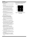
In areas like the following, there may be the case that
infrared switches do not function correctly. (If these
are unavoidable, use an appropriate cover.)
(1) Where unit (operation panel) is exposed to direct
sunlight, reflection of light onto window pane and
diffused light reflection.
(2) Where smoke and steam may occur.
(3) Where exposed to direct snow, ice or mud.
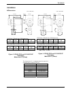
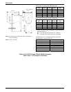
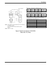
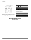
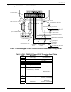
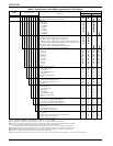
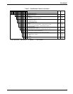
Ordering Information
1. When ordering the LF410 series flowmeters, refer
to Tables 6 and 7 (Type Specification Codes).
An entry must be made for each of the columns in
each of these tables.
2. Fluid characteristics:
(1) Type of fluid to be measured and its characteristics
(2) Fluid temperature
(3) Fluid pressure
(4) Electrical conductivity of the fluid
3. Measuring range
4. I/O function setting
5. Ordering scope:
Flow calibration data: (required or not)
6. Other items
Specifications other than standard items
Consult a Toshiba representative before
ordering when choosing materials of the wetted
parts such as lining, electrodes, and grounding
rings.