


TIC-LF414C
4
Conditions when power fails:
Parameter setting values are stored in non–volatile
memory and the values will be restored when the
power returns to normal condition. The outputs and
display will remain as follows when power fails.
• Current output: 0mAdc
• Digital output: OFF
• LCD display: No display
• PROFIBUS: No communication
Power supply:
One of the following can be selected:
• 100 to 240Vac, 50/60Hz (std.)
(allowable voltage 80 to 264Vac)
• 24Vdc (allowable voltage 18 to 36Vdc)
• 110Vdc (allowable voltage 90 to 130Vdc)
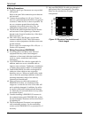
Surge protection:
Arresters are installed in the power supply and a
current signal output circuit to help protect the meter
from lightning and improve personnel safety.
Case: Aluminum alloy (equal to IP67)
Coating: Acrylic resin-baked coating, pearl–gray
colored
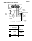
Cable connection port:
Cable glands —
LF610 and LF612 without cFMus Approval:
Provided as standard, OD of cableφ11~13mm
Material Nylon 66
G (PF) 1/2 male screws.
LF610F and LF612F with cFMus Approval:
Not provided, 1/2–14NPT male screws are
required.
Applicable diameter —
0.433 to 0.512 inch (11 to 13mm)
Note: When PROFIBUS option is specified, cable gland size is
φ6~8mm for signal cable, φ11~13mm for power cable
Vibration resistance:
No resonance to the following levels of vibration:
• 10 to 150Hz with acceleration of 9.8m/s
2
• Vibration of 30Hz with 29.4 m/s
2
in 4h in each
direction will not cause any defect to unit.
Note: Avoid using the flowmeter in an environment with
constant vibration.
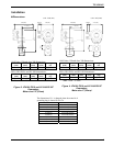
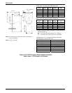
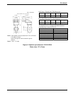
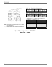
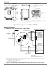
Dimensions and Weights:
See Figure 9 (for Separate type)
MTBF:
Converter: 220,000 hours (25 years) at 77 °F (25 °C)
based on strict military specification
MIL-HDBK-217F
Detector: 350,000 hours (40 years) at 77 °F (25 °C)
based on strict military specification
MIL-HDBK-217F
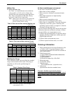
PED matrix in each flange connection.
The following sizes fall under the category for PED
in each flange connection when the meter ships to
EU. All of them had complied with it from a notified
body.
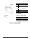
Table 1. PED matrix in each flange connection
Flange standard Meter size
DIN PN 16 and BS 16
6 to 16 inch
(150 to 400mm)
DIN PN 10 and BS 10
10 to 16 inch
(250 to 400mm)
ANSI 150 and JIS10K
6 to 16 inch
(150 to 400mm)