


TIC-LF414C
10
矢視A
信号ケ ーブル
グランド
電源ケ ー ブルグ ランド
封止栓
励磁ケ ーブル グ ランド
電流出力ケーブ ル グラン ド
接地端子
(M4)
取付金具
4-
φ
11
取付金具
82
(36) 156
13
151
178
200
151
74 ± 0 . 3
矢視
A
25
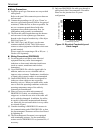
LCD 表示器
赤外線スイッ チ
ケーブルグランド
(
単位
:
mm
)
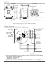
Excitation cable groun
d
5.94
(
151
)
5.94(151)
2.91(74)
4
–
φ 0.43(φ 11)
Attachment
LCD display
7.01
(
178
)
7.87(
2
00)
IR Switch
Cable ground
6.14(156) 1.42(36)
0.98
(
25
)
3.23(82)
0.51
(
13
)
I/O cable ground
Gr ound terminal
(M4)
Power supply cable ground
Blind screw
Signa l cable ground
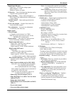
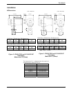
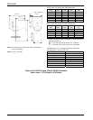
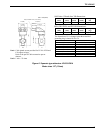
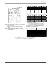
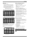
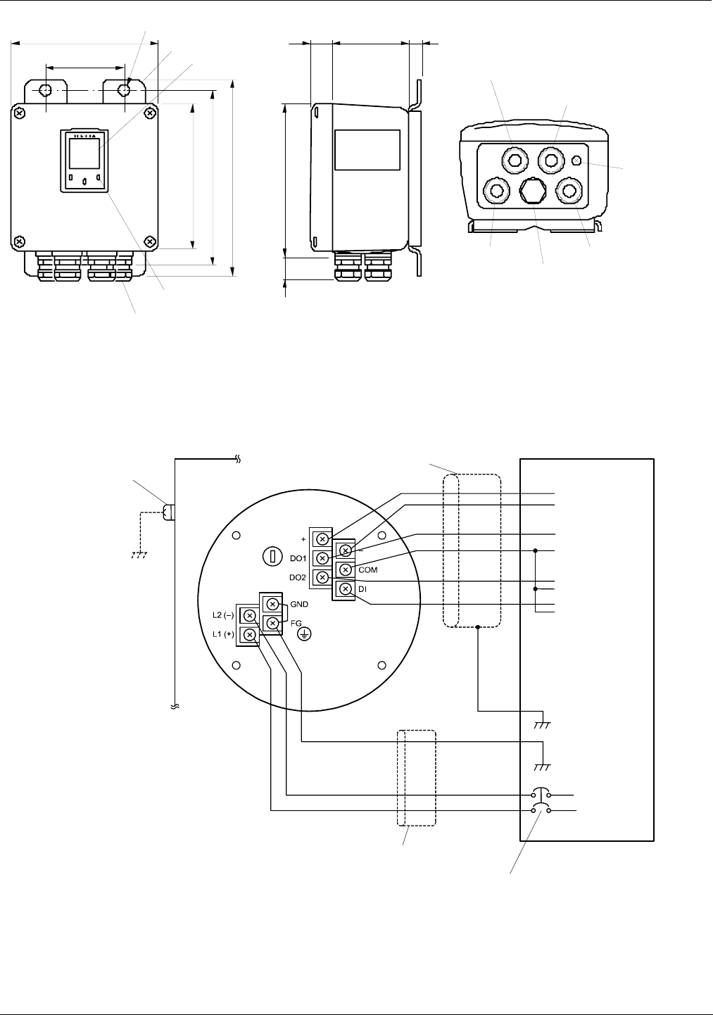
Figure 9. Separate type converter LF612 and LF612F
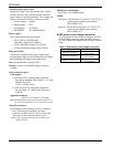
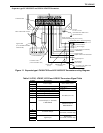
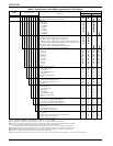
External Connections
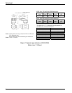
Combined type LF410/LF610 and LF414/LF610F flowmeters
Ground terminal
Intermediate
voltage (IV) wire,
5.5mm
2
or more.
To be grounded
with 100Ω or less
ground resistance.
Power Cable (CVV)
Power Switch
*
1
(External double-pole power switch)
I/O Cable (CV
V
-S)
Instrumen
t
Panel : Ordered separatel
y
Current output
(4~20mAdc) or
PROFIBUS
Digital Output 1
Digital Output 2
Digital Inpu
t
(20 to 30Vdc)
Grounded with
100Ω or less
ground resistance
Grounded with
100Ω or less
ground resistance
Power suppl
y
Signal common
for DI and DO
*1 Locate an external double-pole power switch on the power line near the flowmeter within easy reach of operation.
Use the appropriate switch rating as shown below:
Switch rating: 250Vac, 6A or more
In rush current: 15A or more
Figure 10. Combined type LF410/LF610 and LF414/LF610F flowmeters Wiring Diagram
Unit : inch(mm)
Weight: Approx. 7 lb (3.5 kg)
N
ote: Cable glands are not provided for LF612F cFMus approved type.
Refer to the part Cable connection port at detector.
Note: 1 inch = 25.4 mm