


TIC-LF414C
11
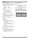
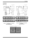
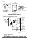
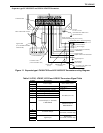
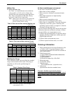
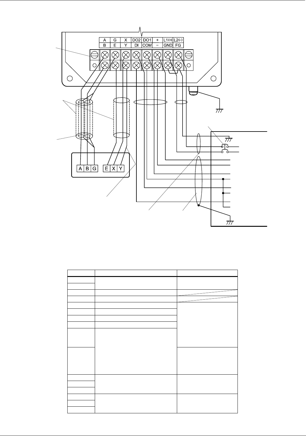
・Separate type LF410/LF612 and LF414/LF612F flowmeters
Terminal board
Connected detecto
r
IV wire
5.5 mm
2
or more
Power switch
(External double-pole power switch )
Thick walled steel conduit
Signal cable
Power cable
(CVV)
Digital input cable
(CVV-S)
Current output (4~20mAdc)
or PROFIBUS
Grounded with 100Ω or less
ground resistance
(2-wire shielded hard-rubbe
r
sheathed cable)
(3-wire hard-rubber cable)
Digital output 1
Signal common for DI and DO
Digital output 2
Digital input
(20~30Vdc)
Power supply
[Instrument panel : ordered separately]
Figure 11. Separate type LF410/LF612 and LF414/LF612F flowmeters wiring Diagram
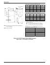
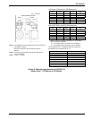
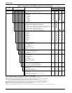
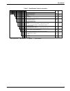
Table 2. LF610, LF610F, LF612 and LF612F Converters Signal Table
Symbol Description Cable
L1 (+)
L2 (-)
Power supply Power cable (CVV)
GND Ground (for arrester)
FG Frame ground
DI Digital Input (20~30Vdc)
DO1 Digital Output 1
DO2 Digital Output 2
COM Signal Common for DI, DO1, DO2
+
I/O cable (CVV-S)
-
Current Output (4~20mAdc)
or PROFIBUS
Shielded cable for
PROFIBUS-PA
X
Y Excitation Output
E
Excitation cable
(for LF612, LF612F only)
A
B Signal Input
G
Signal cable
(for LF612, LF612F only)
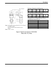
Grounded with 100Ω or less
ground resistance
Excitation cable
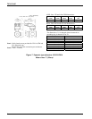
Grounded with 100Ω or less
ground resistance