


TIC-LF414C
2
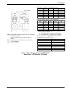
Power consumption:
17W(27VA) or less
19W(29VA) or less (with PROFIBUS)
Conformance to European Community Directives:
EMC directive 89/336/EEC
The low voltage 93/68/EEC
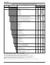
PED 97/23/EC (Note 1)
Note : See Table 1 for detail.
Approved hazardous location certifications:
Model: LF414/LF610F and LF414/LF612F
cFMus explosion proof:
FM Class I, Division 2, Groups A,B,C, and D.
FM Class II, Division 2, Groups E, F and G.
FM Class III.
Detector and converter combination:
LF410/LF610: Combined type for standard
specification.
LF410/LF612: Separate type for standard
specification.
LF414/LF610F: Combined type with Ex approval
of Class I, Division 2 (cFMus).
LF414/LF612F: Separate type with Ex approval of
Class I, Division 2 (cFMus).
Mount-Anywhere Technology:
With TOSHIBA’s unique patented magnetic field
distribution technology, the meter is highly immune
to upstream flow disturbances.
A minimum of 1D (one diameter) length of upstream
straight pipe from the flange is required to maintain
the performance specification.
Note : The test results were obtained and demonstrated at
TOSHIBA's flow calibration facility, Fuchu Japan.
Model LF410 and LF414 Detectors
Mounting style: Wafer type
Fluid pressure:
-
15 to 300psi, or
-
1.0 to 20 bar
(
-
0.1 to 2.0MPa)
Note: The test pressure before shipping from the factory is
equal to twice the nominal pressure rating of the
customer specified flange connection during 15
minutes.
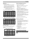
Connection flange standards:
ANSI 150, ANSI 300, BS10, BS16, DIN PN10,
DIN PN16, JIS10K, JIS16K, JIS20K
Principal materials:
Case —
1” to 4” (25 to 100mm): stainless steel
1/2”, 6”, and 8” (15, 150, 200mm): carbon
steel
Linings —
1/2” to 4” (15 to 100mm):
Ceramic tube (std.) & Teflon PFA (opt.)
6” to 8” (150 and 200mm): Teflon PFA
Electrodes —
Type-Super smooth, polished with self cleaning
finish, and non stick shape
316 stainless steel (std.)
Hastelloy C equivalent (std.) (in case of Teflon
PFA lining)
Note: Electrodes are electro-chemically polished after
mechanically buffed.
Grounding rings — 316 stainless steel (std.)
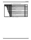
Note: See Table 6 for optional materials and other
related information.
Measuring tube material — 304 stainless steel (in
case of Teflon PFA lining)
Coating —
1” to 4” (25 to 100mm):
No coating (stainless steel body).
1/2”, 6”, and 8” (15, 150, 200mm):
Corrosion resistant phthalic acid resin coating
with pearl-gray colored.
Heat shock resistance: for a ceramic tube detector
Heating: ΔT ≤ 302
°F/0.5sec (150 °C/0.5sec)
Cooling: ΔT ≤ 212
°F/0.5sec (100 °C/0.5sec)
Note: The above means that the ceramic tube detector
withstands the shock of sudden heating
(temperature difference 150°C or less per
0.5seconds) and sudden cooling (temperature
difference 100°C or less per 0.5seconds).
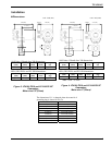
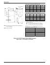
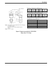
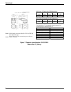
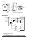
Dimensions and weights: See Figures 3 to 8.
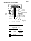
Cable connection port: for separate type detectors.
Cable glands —
LF410 (without cFMus approval):
Provided as standard, R(PT) 1/2 male
screws.
LF414 (with cFMus approval):
Not provided, 3/4-14NPT male
screws are required.
Applicable diameter —
0.433 to 0.512 inch (11 to 13mm)
Model LF610 and LF612 converters
Input signals
Analog signal — the voltage signal from detector,
proportional to process flow rate (for LF612
separate type converter).