


172-082010_400 I Series Software Page 8 of 35
1.5. Flow Alarms
If the flow alarm enable is set then the flow value (“f”) is compared to the high flow alarm
limit and the low flow alarm limit points. When the current flow reading is above the high flow
alarm or below the low flow alarm limit then the flow alarm counter is incremented. If the
flow alarm counter exceeds the flow alarm delay then the respective alarm bit is set for both
the alarm and the alarm acknowledge.
If the flow warning enable is set then the flow value (“f”) is compared to the high flow warning
limit and the low flow warning limit points. When the current flow reading is above the high
flow warning or below the low flow warning limit then the flow warning counter is
incremented. If the flow warning counter exceeds the flow warning delay then the respective
warning bit is set for both the warning and the warning acknowledge.
If the current flow value is not outside of the limits for any alarms then the alarm counter is
set to zero. If the current flow value is not outside of the limits for any warnings then the
warning counter is set to zero. Any alarms or warnings that are not outside of the limits will be
reset. However the alarm acknowledge and warning acknowledge are not reset when the
condition recovers. A message must be received by the communications channel to reset these
values.
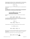
1.6. Totalizers
The current flow is divided by the product of Time correction Factor (TcF) and the number of
flow readings per minute. This result is added to the current value of the totalized flow.
If the current flow reading is greater than 1% of the rated full scale flow then the flowing time
total is incremented by the time required to take a flow reading. (typically 1/16
th
of a
second).
1.7. Setpoint selection
If the product configuration (s64) is setup to signal that the instrument is a flow controller then
the instrument must send signals to the on-board PID (proportional, integral, differential)
controller to tell it what the currently desired flow rate is. The PID will adjust the valve drive
up or down as necessary until the current measured sensor output equals the requested flow
rate.
The user may request a flow setpoint in two ways. One is via the analog setpoint input (s26).
The user may also send a digital command signal over the network. The active input is chosen
by setting the following bits in the MFC Configuration word (v2).
bits 7(msb), 6: Field of two bits selects source of command setpoint:
00 = invalid assignment, choice will be forced to default (network)
01 = command setpoint taken from network command
10 = command setpoint taken from setpoint A/D converter
11 = invalid assignment, choice will be forced to default (network)
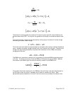
The analog setpoint Sp value calculated above divided by full scale range of the analog input
(Afs)
1
determined from the product configuration word s64. This value is reported via v7 in %
of full scale. This value is also multiplied by the full scale flow value g2 and reported via v6 as
the command value in engineering units.
1
For 4-20 ma units the Afs = 16 and for 1-5 vdc units the Afs = 4.
62 vg
Afs
Sp
=