172-082010_400 I Series Software Page 15 of 35
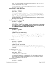
item 9 :flow warn enable:
read S9(cr) or *[aa]S9(cr)
Sample reply: 1(cr)>
write S9=1.0(cr) or *[aa]S9=1.0(cr)
This is a binary value that when enabled it will allow flow values that exceed warning
limits for a time longer than specified by the flow warn delay to set bit 15 or bit 14 of
the warning status word. Setting this bit also sets the bit 14 of the MFM config word
(S2).
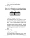
item 10:flow warn delay:
read S10(cr) or *[aa]S10(cr)
Sample reply: 0 S(cr)>
write S10=1.0(cr) or *[aa]S10=1.0(cr)
This defines the length of time in seconds between the start of an error condition until
the time it is reported by the warn status word. A setting of 0.00 will result in an
immediate response.
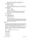
item 11:FS volts: (read only)
read S11(cr) or *[aa]S11(cr)
Sample reply: 5.000 VDC(cr)>
This reports the full scale analog output as defined by the product configuration byte
(S64).
item 12:flowing hours: (read only)
read S12(cr) or *[aa]S12(cr)
Sample reply: 1234.65 H(cr)>
This is the total time that flow (>2%FS) has been passing through the instrument. This
cannot be reset to 0. Useful for determining maintenance schedules.
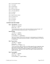
item 13:temperature: (read only)
read S13(cr) or *[aa]S13(cr)
Sample reply: 22.68 Deg Celsius(cr)>
This item reports the current temperature indicated by the temperature sensor
mounted on the processor pc board. It will typically indicate a temperature that is
slightly warmer than the ambient temperature outside of the instrument.
item 14:precision:
read S14(cr) or *[aa]S14(cr)
Sample reply: 5(cr)>
write S14=7(cr) or *[aa]S14=7(cr)
This item controls the number of places after the decimal point that the output data
will have. This can be any number from 0 – 8.
item 16:user zero offset:
read S16(cr) or *[aa]S16(cr)
Sample reply: 0.03187596(cr)>
write S16=0(cr) or *[aa]S16=0(cr)


