


172-082010_400 I Series Software Page 6 of 35
1. Operating Algorithm
1.1. Hardware description
There is a serial communications port for digital communications, an analog (0-5 volt/0-10
volt/4-20 ma/0-20 ma) analog output proportional to the flow rate. There are two isolated
open-collector alarm pins.
The flow signal is derived on a separate sensor board and supplied to the main processor
digitally via an IIC bus and is also supplied as 0-0.7 volt analog signal referred to a 2 volt
reference. There is also an eeprom on board the sensor that uses the IIC bus for
communication. All calibration and configuration information is stored on the sensor eeprom
so that the main board may be replaced without affecting calibration.
A Motorola MC9S12 with 128K bytes of flash ram is being used for the main processor.
1.2. Flow Reading
The flow reading starts with acquiring a value (AD) from the sensor A/D. This value will be in
counts (16 bits signed, -32768 – 32767 corresponds to -2.048 volts – 2.047 volts). This value is
converted to a voltage reading and is available via the s40 command. The zero flow sensor
output value (AD0) in volts (available via s16 command and set using the “zro” command) will
be subtracted from this. The result is divided by the sensor output value when flowing 5 sccm
of nitrogen (SFS) in volts (see “s 45” command) the resultant value will be a floating point
number between -2 and +2 typically between 0 and +1.
This resultant sensor value is linearized with a normalized polynomial with a linear and a 3
rd
order component. The coefficients of this polynomial have been calculated such that the sum
total of the coefficients is 1.00. The 3
rd
order value (B) is set for nitrogen with the “s 43”
command, the 5
th
order value (C) is set for nitrogen with the “s 44” command. The linear
value (A) is calculated from the fact that A + B + C = 1 and can be read with the “s 42”
command. Since each gas creates a different non-linear response in the flow sensor each gas
must be linearized using a different polynomial. Each gas has two factors which are used to
correct the for the varying gas sensitivities of the sensor. The linear part is called the gas
correction factor GCF (available via the G9 command, from GasDataTables.xls) and the
coefficient that multiplies the higher order term is referred to as the gas “z” multiplier (Gz,
available with the g3 command).
The resultant (SL) is also a floating point value typically (but not always) between 0 and 1.
This resultant linear sensor value is adjusted with another gas dependent normalized
polynomial to correct for the non-linearity of the laminar flow element. This polynomial has a
linear and a 2
nd
order component. The coefficients of this polynomial have been calculated
such that the sum total of the coefficients is 1.00. The 2
nd
order value (E) is set with the “g10”
command and the 4
th
order value (F) is set with the “g11” command. The linear value (D) is
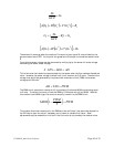
calculated from D + E + F = 1. It cannot be set or read. The resultant (SHL) is also a floating
point value typically (but not always) between 0 and 1. Changing the active gas will select a
GzCCGzBB
⋅
=
′
⋅
=
′
,
()
(
)
[
]
SLGCFSCSBSA =
′
+
′
+ )(
53
S
SFS
ADAD
=
−
0