


140-072011 200/202 Series Page 22 of 24
B) If P
u
>2P
d
, use formula 1; otherwise use formula 2.
C) Use a consistent set of units for pressure, flow, and density (i.e all lengths, masses, times in the same
units, cm, ft, kg, sec etc.) 1 liter/minute = 1.667 x 10
-5
m
3
/sec, 1 gm/liter = 1 kg/m
3
, 1 psia = 6895
kg/m*sec
2
, 1 Pa = 1 kg/m*sec
2
,
D) This formula provides approximate results that tend to be undersized because it neglects pressure
drops internal to the flow controller, compressible gas effects and temperature effects. Multiply the result
by ≈1.5 to get the expected minimum orifice size that can reliably pass the desired flows at the expected
pressures.
Where:
Formula 1: Formula 2:
D
= Orifice Diameter
Q
= Flow rate in standard volumetric unit (slm, sccm, scfh)
P
0
= Standard Pressure (760 Torr, 101.325 kpa)
P
u
= Upstream pressure in absolute units (use minimum expected value)
P
d
= Downstream pressure in absolute units (use maximum expected value)
γ
= Ratio of specific heats, ≈ 1.2 for monatomic gases, 1.4 otherwise
ρ
0
= Density of gas @ standard pressure and temperature of flow unit
π
= Pi (3.1415…)
σ
= Specific gravity of gas (ratio of gas density to density of air)
Choose the available orifice with the closest diameter that is larger than the calculated diameter. Orifice
diameters (inches) available are 0.001, 0.002, 0.003, 0.007, 0.014, 0.032, 0.042, 0.052, 0.070. Contact
factory to order new orifice.
As an example, if the maximum controlled flow will be 10 slm of air with an upstream pressure of 50
psig and exhausting to atmospheric pressure the minimum orifice diameter calculated from the previous
equation would be 0.0225 inches. The next larger orifice that has a diameter of 0.032 inches should be
installed.
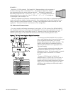
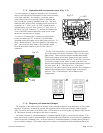
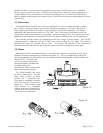
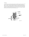
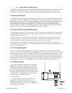
4.7.1. HFC-202 Orifice
To change the orifice in the HFC-202 series, turn the instrument upside-down and turn the orifice
counterclockwise with a 9/64" Allen wrench until it stops coming out. Then grasp the exposed orifice end
and pull it straight out. See Figure 4.2.
Prior to reinstallation of the orifice, inspect the two O-rings mounted on it for damage. Replace if cut or
gouged.
()
4
2
00
2
8
π
ρ
σ
P
PPP
Q
D
dud
−
=
4
2
00
2
2
16
π
ρ
γ
σ
P
P
Q
D
u
=