


140-072011 200/202 Series Page 16 of 24
3. Theory of Operation
This section contains a functional description of Hastings flow controllers. Detailed schematics and
parts lists can be obtained by contacting Hastings using the contact information found at the end of this
document. In this section and other sections throughout this manual, when a power supply is mentioned,
it is assumed that the customer has a Hastings Power Supply. These sections are not applicable if another
type of power supply is used.
3.1. Overall Functional
Description
The Hastings flow controller consists
of a sensor, electronic circuitry, a shunt
and a valve. The sensor measures the
flow rate from 0 to 10 sccm of the gas to
be metered. The shunt divides the flow
such that the flow through the sensor is a
precise percentage of the flow through
the shunt. The flow through the sensor
and the shunt is always laminar. The
circuit board amplifies the sensor output
and uses this output to control the valve
position. The valve is an automatic
metering solenoid type; its height off the
seat is controlled by the voltage in its
coil. All of these components working
together result in a fast, stable flow
controller.
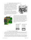
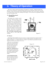
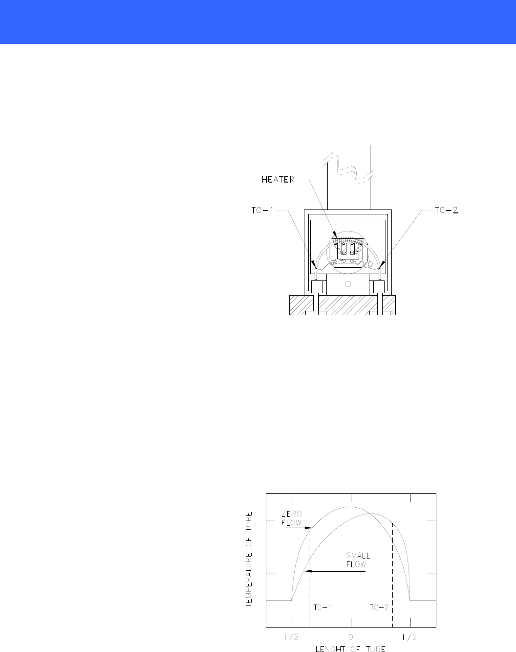
3.2. Sensor
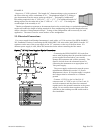
The Hastings HFM-200/HFC-202 series operates on a unique thermal electric principle whereby a
metallic capillary tube is heated uniformly by a resistance winding attached to the midpoint of the
capillary (see Figure 3.1). Thermocouples TC-1 and TC-2 are welded at equal distances from the
midpoint and develop equal outputs at zero flow.
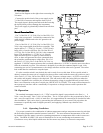
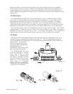
When flow occurs through the
tubing, heat is transferred from
the tube to the gas on the inlet
side, and from the gas back to
the tube on the outlet side
creating an asymmetrical
temperature distribution (see
Figure 3.2). The thermocouples
sense this decrease and increase
in the capillary tube temperature
and produce a millivolt output
signal proportional to that
change.
For a constant power input,
the differential thermocouple
output is a function of the mass
flow rate and the heat capacity
of the gas. Since the heat
capacity of many gases is
Figure 3.1
Figure 3.2