


140-072011 200/202 Series Page 12 of 24
2.6.2. Zero Check
Turn the power supply on if not already energized. Allow for a 1 hour warm-up. Stop all flow through
the instrument and wait 2 minutes. Caution: Do not assume that all metering valves completely shut off
the flow. Even a slight leakage will cause an indication on the meter and an apparent zero shift. For the
standard 0 - 5 VDC output, adjust the zero potentiometer located on the lower outlet side of the flow
meter until the meter indicates zero. For the optional 4 - 20 mA output, adjust the zero potentiometer so
that the meter indicates slightly more than 4 mA, i.e. 4.03 to 4.05 mA. This slight positive adjustment
ensures that the 4-20 mA current loop transmitter is not in the cut-off region. The error induced by this
adjustment is approximately 0.3% of full scale. This zero should be checked periodically during normal
operation. Zero adjustment is required if there is a change in ambient temperature, or vertical orientation
of the flow meter/controller.
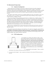
2.6.3. High Pressure Operation
When operating at high pressure, the increased density of gas will cause natural convection to flow
through the sensor tube if the instrument is not mounted in a level position. This natural convection flow
will be proportional to the system pressure. This will be seen as a shift in the zero flow output that is
directly proportional to the system pressure.
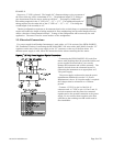
2.6.4. Blending of Gases
In the blending of two gases, it is possible to maintain a fixed ratio of one gas to another. In this case,
the output of one flow controller is used as the reference voltage for the set point potentiometer of a
second flow controller. The set point potentiometer then provides a control signal that is proportional to
the output signal of the first flow controller, and hence, controls the flow rate of the second gas as a
percentage of the flow rate of the first gas.
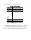
EXAMPLE: Flow controller A has 0 - 100 slpm range with a 5.00 Volt output at full scale. Flow
controller B has 0 - 10 slpm range with a 5.00 Volt output at full scale. If flow controller A is set at 80
slpm, its output voltage would be 4.00 Volts (80 slpm/100 slpm x 5.00 Volts = 4.00 Volts). If the output
signal from flow controller A is connected to the command potentiometer of flow controller B, it then
becomes a variable reference voltage for flow controller B proportional to the flow rate of flow controller
A.
If the set point potentiometer of flow controller B is set at 50% of full scale, and the reference voltage
from flow controller A is 4.00, then the command signal going to flow controller B would be 2.00 Volts
(4.00 Volts x 50.0% = 2.00 Volts). The flow of gas through flow controller B is then controlled at 4 slpm
(2.00 Volts/5.00 Volts x 10 slpm = 4 slpm).
The ratio of the two gases is 20:1 (80 slpm/4 slpm). The % mixture of gas A is 95.2 (80 slpm/84 slpm
and the % mixture of gas B is 4.8% (4 slpm/84 slpm).
Should the flow of flow controller A drop to 78 slpm, flow controller B would drop to 3.9 slpm, hence
maintaining the same ratio of the mixture. (78 slpm/100 slpm x 5 Volts = 3.90 Volts x 50% = 1.95 Volts;
1.95 Volts /5.00 v x 10 slpm = 3.9 slpm; 78 slpm: 3.9 slpm = 20:1)
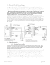
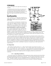
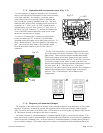
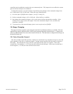
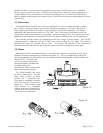
2.7. Operation with External Devices
2.7.1. Operation with a Hastings power supply.
There are two controls for each flow controller connected to a Hastings power supply. A switch labeled
“OPEN; AUTO; CLOSED” (valve override THPS 400 only) and a potentiometer labeled
“COMMAND”. For normal operation, the valve override switch will be in the “AUTO” position. The
“CLOSE” position removes all power from the valve, shutting off flow regardless of the command pot
setting. The “OPEN” position applies full available valve voltage to the valve, causing it to open,
regardless of the command pot setting. The “OPEN” position is useful for purging systems. It is
recommended that the valve override switch not be left in this position for extended periods of time, with
no flow through the controller, as a small positive zero shift may be observed.