


140-072011 200/202 Series Page 13 of 24
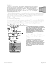
The “COMMAND” pot adjusts the Analog command signal sent to the flow controller. The setting for
each controller connected to the power supply can be observed. (Depending on how the power supply
was set up, the display could indicate in flow units or percent of full scale).
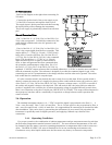
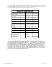
Hastings Power Supply Feature Guide
Feature Model 40
Power Pod 100
Power Pod 400
Digital Readout
9 9 9
±15 Volts
9 9 9
Analog Outputs
9 9 9
Controller
9 9
Analog Control
9
Front Panel Override
9
9
Totalizer
9
4 -20 mA
9
9
Ratio Control
9
Alarms
9 9 9
Multi-Channel Display
9
Conversion Factors
9 9 9
Communications RS232 RS232/RS485
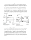
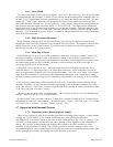
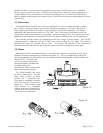
2.7.2. Operation with a Power Supply other than a Hastings
The flow controller must be connected to the power source as specified in section 2.6. In general, a 0 -
5 VDC command signal proportional to the intended flow (0 Volts = zero flow; 5 Volts = 100% of rated
flow) must be applied to pin 14 of the DA-15 (15 Volt), Pin 3 of the DE-9 (24 Volt) connector. A 0 - 5
VDC signal proportional to the flow rate through the instrument will be present on pin 6 of the DA-15
(15 Volt), Pin 2 of the DE-9 (24 Volt) connector. The control mode is selected via pin 8 of the DA-15
(15 Volt), Pin 6 of the DE-9 (24 Volt) connector. Apply > 10 Volts for full open, < 0 Volts for closed
and allow the override to float for flow proportional to the command voltage. Refer to your power supply
manual for the specifics of implementing these parameters.