


140-072011 200/202 Series Page 15 of 24
controller circuit establishes control at the new command point. This jumper does not affect the system
gain and will not dampen out oscillations.
To adjust the response, you need a means of producing a step change in the command voltage from
10% of full scale to 100% of full scale. Follow the steps outlined below:
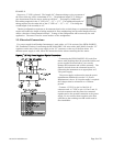
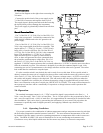
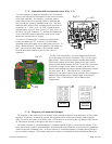
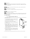
1) Cover the pins of JP4/JP6 with a jumper. (see fig. 2.2 & fig 2.3)
2) Set the command voltage to 10% of full scale. Allow the flow to stabilize.
3) Step change the command voltage to 100%, and observe the flow through the controller. If the
overshoot is too large, remove the jumper. Reset the command voltage to 10%, and allow the
controller to stabilize.
4) To prevent loss of the unused jumper, place it over one pin only on JP4/JP6.
2.8. Range Changing
The range of the flow controller can be changed in the field if recalibration facilities are available. The flow
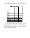
controller may require a different orifice, which can be purchased separately from the factory. A listing of the
orifices available and their flow rates can be found in Section 5.0. The instructions to change the flow range can
be found in Section 4.6.
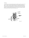
2.9. Valve-Override Control
The valve override control line provides a method to override the loop controller and open or close the
valve regardless of the flow or command signals. During normal operation this line must be allowed to
float freely. This will allow the loop control to open and close the valve as it requires. If the valve
override line is forced high (> +10 Volts) the valve will be forced full open. If the valve-override line is
forced negative (< 0 Volts) the valve will be forced closed.