


140-072011 200/202 Series Page 10 of 24
EXAMPLE:
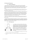
Suppose a 4” LFE is selected. The length of 4” diameter tubing or pipe, upstream of
the sensor inlet tap, will be a minimum of 20“. The minimum length of 4” tubing or
pipe downstream from the sensor outlet tap will be 4”. The length of additional 4”
inlet tubing required for the 4” LFE is 20” – 2.5” = 17.5”. The additional length of 4”
tubing required for the outlet side of the 4” LFE is 4” – 2.5” = 1.5”. This brings the
overall length of the assembly to 19”.
Tubular configurations upstream or downstream that involve conical shapes or optimized expansion
nozzles will reduce the length of tubing required for flow straightening, but the actual length necessary
will be a function of that geometrical shape. Testing of that configuration will be necessary for each
application. The same is true for screen meshes or flow straighteners.
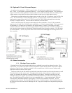
2.5. Electrical Connections
If a power supply from Hastings Instruments is used with a ±15 Volt version of the HFM-200/HFC-
202, installation consists of connecting the HFM-200/HFC-202 series cable (#AF-8AM) from the “D”
connector on the rear of the power supply to the “D” connector on the top of the flow meter. If a
different power supply is used, follow the instructions below when connecting the flow meter.
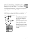
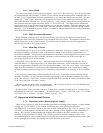
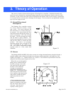
Bipolar (±15 Volt) Power Supply to Bipolar Connections
Connecting the HFM-200/HFC-202 series flow
meters with anything other the prescribed cables and
power supplies discussed above, can severely
damage the instrument and void the warranty. The
figure to the left shows the schematic layout for
connecting the instrument to an appropriate ±15
Volt power supply.
The power supply used must be meet the power
requirements delineated in section 2.2 (Power
Requirements) above. If a bipolar supply is required
the voltages must be referenced to a common
ground.
Connect -15 VDC to pin 9 of the DA-15
connector and +15 VDC to pin 11. Pins 5 and 12
are both commons and they must be connected
together and to the ground connection at the power
supply. Do not connect them together at the flow
controller as the resulting crosstalk could result in
flow instabilities.