


Spannunsabfall auf dem positiven Kabel auszugleichen.
Ein optionale Extra, das komplet mit einem Display geliefert wird. Siehe Skizze5-6fürdieBedienung der
Fernbedienung.
Sobald das Gerät angeschlossen ist, überwacht es die Eingangsspannung von der Starter-Batterie. Ist die
Spannung > 11Vdann schaltet das Gerät ein. Stellt es fest, dass die Spannung < 13V ist, dann schaltet es
automatisch nach 15 Minuten in den Schlafmodus und wartet dort so lange, bis die Spannung wieder über
13V ist.
Wird ein Ladesystem auf der Starterbatterie gestartet (z.B. Lichtmaschine, Ladegerät, Solarzelle,
Windgenerator, etc.), dann steigt die Spannung und das Gerät schaltet sich ein. Die ersten 3 Minuten arbeitet
das Gerät nur im Standby, um der Starterbatterie die Möglichkeit zur Ladung zu geben. Dabei blinkt die
LED 16. Dieser "auto-pause-modus" kann durch über die Fernbedienung deaktiviert werden.
Nach 3 Minuten wandelt sich das blinken in ein konstantesAufleuchten, um oder schaltet die Ladung ein.
Dabei wird sich die Last auf der Lichtmaschine erhöhen, da die Ladung jetzt zur Servicebatterie gepumpt
wird.Alle 20 Minuten schaltet sich die Ladung ab, um wieder der Starterbatterie die Möglichkeit zur
Nachladung zu geben.
Sobald die Ladeschlussspannung erreicht ist, leuchtet die Timer-LED 17 auf und das Gerät beginnt mit der
Ausgleichsladung. Nach einer automatisch berechneten Zeit, abhängig vom eingestellten Batterietyp, bleibt
die Ladung in derAusgleichsladung. Erst nach Ablaufen dieser Zeit (den Zeit kann man sich in der
Fernbedienung anzeigen lassen), schaltet das Gerät in die Erhaltungsladung (13.8 - 13.5V).
Sollte sich die Spannung der Service-Batterie auf weniger als 12V verringern (z.B. bei einer hohen
Belastung mit einem Wechselrichter, etc), dann wird der Ladevorgang wieder von vorne wiederholt.
Wird der Motor (Lichtmaschine) oder der Windgenerator abgeschaltet, so schaltet sich automatisch das
Gerät nach ca. 15 Minuten ab. Dazu muss die Spannung am Eingang unter 13V fallen. Da die
Leerlaufspannung bei allen Batterietypen < 13V ist, so sollte es hier kein Problem geben. Manchmal kann
dieses auch länger daürn, da erstmal die Oberflächenspannung der Batterie abgebaut werden muss.
Testen Sie die Batteriespannung. Diese sollte an der Batterie über 11Vliegen. Starten Sie den Motor. Nun
sollte die Spannung auf der Starterbatterie > 13V sein. hat. Ein remote panel als eine zusätzliches Extra
erhältlich.
Wenn alles korrekt funktioniert, wünschen wir Ihnen viel Spass mit diesem innovativem Gerät.
Alle von uns genannten Spannungen beziehen sich auf 20°C. Wenn Sie einen Batterietemperatursensor
anschliessen, weichen die Ladespannungen entsprechend ab, da diese jetzt temperaturkompensiert sind.
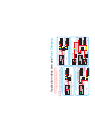
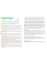
Hier wird lediglich dieArt der Batterie, die von dem Benutzer eingestellt wurde, angezeigt.
Grün: EXIDE Gel-Batterie
Rot: geschlossene Säurebatterie &AGM;
Grün (flashing): Gel- &AGM Batterien (USA Spezifikation)
Fernbedienung: (13)
ErsterAnschluss und Test:
Was ist, wenn beimAnschluss gar nichts passiert?
Wichtig!
LED 14 = Batterie Typ
Funktionen und Bedeutungen der Leuchtdioden:
LED (3 down) will flash slowly. This indicates that the unit is working but is inactive for the first 2.5 minutes to allow the
engine battery to recover a little.
After about 2.5 minutes the green light will stop flashing and go onto green continuous, or shut the system down to rest
mode if the battery voltage is to low.
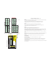
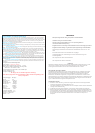
Once the domestic battery reaches a certain voltage (depending on the battery type setting but between 13.5 and 14 volts),
the timer LED will come on and the high charge rate will continue for a calculated time period (never the same), see fig 8,
the box marked “setup”. This time period is determined by what battery type program you select and by the state of charge
of the batteries.After the time is over, the unit drops to float at 14 volts at constant voltage.The unit will attempt to hold
the battery voltage. However, if the output battery falls below about 12.8 volts for more than 15 minutes, the system will
reset to the boost charge mode again.Also, if the input voltage falls below 12.8 volts, the system will assume that the
input is switched off and will switch the system into rest mode to conserve energy. Only if the input voltage rises again,
will the system restart.
then
1) T
If on start up nothing happens,
Reason 1)
Reason 2)
Poor cable on the output when the remote sensor is being used.
Low input voltage.
est the battery voltage. It should be above 11 volts.To see the unit working start up the engine and ensure you are
getting at least 13.5 volts at the battery. always measure voltages at the unit and not the batteries.
The current lights are flashing with no other information lights flashing. The Sterling battery-to-battery charger is so
powerful, that it has got the ability to melt small cables. For example on the 200 amp unit, if a person was to fit a 20 amp
cable, or has bad connections and fits the remote sensing cable, then an unprotected product would try to force 200 amps
down the cable and cause a fire or other serious damage. To avoid this the unit software has a built-in voltage maximum of
1.5 volts differential between the remote sense voltage and the output voltage from the unit. If thecable is too long or too
thin, then the unit would need a very high input voltage at one end of the cable to compensate for the high voltage drops
caused by the bad cablings. However, the system only allows the voltage drop to reach a maximum of 1.5 volts differential
before it starts to limit the current. You will know that the system is controlling the current flow because of bad cables etc,
because the amp meter (the row of LEDs on the front of the unit) will display the approximate current but all the current
lights will flash. This shows the current flow but the current is being restricted due to bad cables or connections.
Increasing the amount of copper will improve the current flow and stop the flashing. It allows the maximum possible safe
current down your installation even if you have poor cables and connections.
The current lights are flashing with the low input voltage light in the information section also flashing. Unlike the above
warning, this could be no problem at all , it simply means that the input voltage to the unit is unable to keep up with the
performance demand of the unit and the units performance is being limited because the input power source ( alternator )
cannot keep the input terminal voltage above 13 volts. This is to protect the starter battery from dropping too low and
causing a failed engine start. There area few possibilities for this, such as the input cable being too thin, or the run to
long. (Remember, it is best to fit the unit close to the input battery to reduce voltage drop.) It could also simply be that at
engine tick-over or low r.p.m. the alternator feeding the starter battery cannot produce enough surplus power to keep up
with the unit’s charging demand, and we are simply reducing the unit’s performance to prevent draining the starter battery.
Neither of the above are safety issues but simply information to make it easier for you to maximise the performance of the
unit either by increasing cable thickness or upgrading your alternator to a bigger one etc.
= High voltage drop between unit output and the
battery (in excess of 3 volts). This is due to a voltage drop in the output cables or bad connectors etc. It would also show
up in the amp meter LEDs flashing to indicate that the current limit safety has already been activated and that your system
is working below par due to poor cabling or connectors. This will be a rare occurrence as the current limiting software
works before this has a chance to operate. However, there are certain possible internal failures which could cause this trip.
In the event of this trip going off, it is not good and the odds are that the unit is defective.
= High internal voltage, the internal boost is too
high and there has been an internal failure of the unit. The unit is defective; please call the Sterling Helpline.
This indicates that the systems performance has been reduced for various
reasons:
SafetyAlarm Functions
The Sterling battery-to-battery charger includes a number of helpful alarms and warnings so that when the user encounters
installation or operational problems, s/he can locate the problem quickly and accurately using the information supplied by
the alarm functions. There are the obvious alarms, then a few not so obvious which we code into LEDs to make them
multi information sources, otherwise our products would run out of space for the l.e.d.s to cover all the information.
Flashing Current Indicator LEDs:
HIGH VOLTAGETRIP, WITH 3x FLASH THEN 3 SEC DELAY
HIGH VOLTAGETRIP, WITH 4x FLASH THEN 3 SEC DELAY