


5) Esstellt sicher, dass keine Spannung im Motormanagement erhöht wird, umAlarm und Schäden am
System zu vermeiden. Egal ob es einAuto oder ein Boot ist.
6) KeineFarhzeuggarantieprobleme, da man nicht auf das Hauptsystem zugreift.
7) BeideBatteriebänke sind voneinander isoliert.
Das Gerät überwacht die Starterbatterie beim Ladevorgang ständig. Es fängt nicht an zu arbeiten, bevor nicht
die Starterbatterie geladen ist und mindestens 13V an dieser erreicht sind. Eine weitere eingebaute Sicherheit
ist, dass das Gerät alle 20 Minuten für 3 Minuten abschaltet, um der Starterbatterie eine weitere Möglichkeit
zur Ladung zu geben. Diese "Auto-Pause"- Funktion ist auch abschaltbar. Vergewissern Sie sich, dass die
Motorbatterie in Ordnung ist. Wenn das Gerät arbeitet wird die Eingangsspannung von 13V- 14V
genommen und auf der Verbraucherbatterieseite auf 14.1V bis 14.8V (je nach Batterietyp) erhöht. Nach
einer gewissen Zeit , die von der Software genau berechnet wurde und die Servicebatterien voll sind, schaltet
das Gerät in den Erhaltungsspannung-modus (13.5V - 13.8V). Es scheint eine einfache simple Idee zu sein,
aber genau diese Einfachheit macht es so Komplex.
Andere Highlights sind die zwei beigelegten Temperaturensoren, der eine für die Batterie, der andere für die
Lichtmaschine. Vorhanden sind ebenfalls einAnschlussr für die Fernbedienung und ein automatischer
Schlafmodus, welcher die Einheit ausschaltet sobald der Motor gestoppt hat. Eine Fernbedienung ist als ein
zusätzliches Extra erhältlich.
Platzieren Sie es so gut es nur geht an einen kalten, trockenen und belüfteten Platz. Meistens ist dieser kühle
Ort mehr ein Wunschdenken, aber trotzdem sollte der Einbauort so kühl und belüftet wie möglich sein. Und
so nah wie möglich an der Eingangs-(Starter-)batterie.
Dieses im Hinterkopf behaltend, werden Sie bestimmt bemerkt haben, dass dieses Gerät mit einem
Kühgehäuse und 3 Lüftern geliefert wurde. Seien Sie nicht überrascht, wenn Sie in Nordeuropa diese Lüfter
nicht laufen sehen, da diese Einheit für eine Umgebungstemperatur von 40Grad Celcius gebaut wird. Sollten
Sie die Einheit in einem heissen Maschinenraum einbaün müssen, wäre das gezwungenermassen in
Ordnung.
BeimAnschluss des Gerätes an die Batterien achten Sie auch gute Belüftung der Batterien, da es beim
Anschluss zum Funkenflug kommen könnte. Beim Konfektionieren vonAnschlusskabeln achten Sie darauf
möglichst starke Kabel zu verwenden. Denn das Gerät misst direkt an den Ein- undAusgängen. Ein
stärkeres Kabel vermindert den Spannunsgverlust und erhöht damit den Wirkungsgrad des Gerätes.
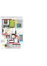
Schliessen Sie zürst das Kabel vom Gerät "BATTERYTO BE CHARGED" zu der Batterie, die effektiv
geladen werden soll.Anschliessend das Kabel vom Gerät "BATTERY INPUT" zur Starterbatterie (die
Batterie, von der die Ladung kommen soll). Erst als letztes das Negativ/Minus-Kabel verbinden.
Achten Sie bitte unbedingt darauf, dass die Spannung an der Eingangsbatterie, wenn der Motor läuft grösser
als 13.5V ist. Somit ist ein Einsatz von Trenndioden zwischen der Lichtmaschine und der Starterbatterie
nicht sinnvoll.
Stellen Sie den Batterietyp gem. Skizze 8, Pkt. 12 ein. Wir unterscheiden zwischen 4 Batterietypen:
1) offene Blei-Säurebatterien, bei denen man den Verschluss der Batterie aufdrehen und mit Wasser
auffüllen kann. Diese sind mitAbstand die besten Batterietypen mit einer schnellenAufladekapazität
und langer Lebensdaür (max 14.8V/20°C). DieAusgleichsladungszeit beträgt zwischen1-3Std. und
wird automatisch berechnet.
2) Gel/EXIDE spec. Diese funktionieren auf EXIDE’s Empfehlungen mit einer Spannung von 14.4V
Wie funktioniert das Gerät?
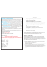
Installation: Siehe fig 8
Anschluss:
Einstellung des Batterietyps
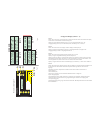
BATTERYINPUT LOW VOLTS
BATTERYOUT PUT LOWVOLTS
low starter battery
BATTERY OVER TEMPERATURE:
SENSOR FITTED/BATTERYTEMPOK
These l.e.ds display 3 different sets of information
on/off:
Alarm
Back ground light:
yellow: This is simply saying that there is
a low voltage at the main battery bank and has no active function. For information only, this usually indicates a
defective alternator or very high demand at low r.p.m.
yellow: LowVoltageWarning: This is saying that there is this
could simply be that the output batteries are so flat that it could take a few hrs to bick up the voltage , ot the unit is
defective and unable to charger the batteries
2 flash then pause etc etc
Red : This shows that the battery temperature sensor has picked up a
temperature in excess of 50 deg C at its source ( where ever you have fitted it ) this will trip the unit until it has been
reset. Please find the fault before resetting
this confirms that the battery temperature sensor is fitted and that all is
o.k., if the sensor is not fitted this l.e.d. will go out
1) when the unit first starts up the l.e.d.s show the battery type selected for the first 30 secs.
2) after 30 secs this block of l.e.d.s become a amp meter showing the current flow through the device
3) if when on operation 2 as per above and the l.e.d.s are showing amps, if the block start to flash then the current has been
limited by the device because of poor cabling on the side of the installer, see the section on saefty in this literature. the
system is still safe but could be improved by improving the cables/connections etc etc.
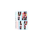
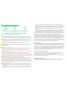
This is the most common and easy installation because of being simply connected to the starter battery. In order to
connect up the d/c battery charger all you need to do is connect one wire from the auxiliarybattery banks to the starter
battery. The starter battery stays between 13-14 volts ( within its limits ) and the domestic battery goes up to 14.4.-14.8. In
order to put a good fast charger into the auxiliary batteries, this is especially good if the battery bank to be charged is not
close to the starter battery , such as things like bow thrusters, or batteries in the boot of cars or lorries
This option shows a standard split charger system on any boat or camper vehicle, which is already installed, and
has been using advanced alternator regulators or any other advanced charging system.An extra battery bank is required
such as a bow thruster, radio battery bank or a generator, for ease of installation simply drop on a d/c battery charger.
This option shows a situation on many boats or camper vehicles where there may be 3 x battery banks, simply put 2
x d/c battery chargers on, and they will ensure both banks are catered for, with no problem. the fact that one battery bank
is further away than the other will make no difference.
This option shows a standard split charger system on any boat or camper vehicle, which is already installed, and
has been using advanced alternator regulators or any other advanced charging system.You will find out, that you wish to
supplement the marine house battery bank by charging with as many other auxiliary charging systems as you can. For
example: if you are running a gen set for 4 hrs per day you may as well put as much power as possible into your main
large house battery bank
Any source can be used. You can even use this system to charger from a old type battery charger , for example if you had a
old constant voltage battery charger and you wished to convert it into a constant current one, then simply put one of these
on the output. Or if you have a single output charger and want a dual output, then simply add one d/c charger to make a
dual charging system
this switches off the unit boost aspect, but cannot prevent the standard diode splitting from working. The
monitoring functions remain in and the only way to know if the unit is switched off is the system within limits ( LED
)which will be off while the boost off will be on screen 3b
: this mutes the alarm system
this switches on and off the back ground light
Green LED, system all o.k.
Low battery input voltage
system disengaged, this is an auto recoverable alarm , such as a high alternator temp trip. This will come back on
when the temperature has reduced
This is a fatal alarm trip, such as high input/output voltage or high battery temp, this will alarm and switch off
-
Low Voltage Warning: (LED on solid )
(LED flashing )
Other application ideas see fig 1-4
Fig 1:
Fig2:
Fig 3:
Fig4:
Remote control panel see fig 5
A:
B:
C:
D:
E:
F:
G:
Point charging. this is a totally new concept developed by Sterling using battery to battery chargers and is ideal for
larger boats with complex systems . see www.sterling-power.com go to downloads, down load information on point
charging.
19
20
21
22 29