


OPERATION
12 ► CT06 User Manual
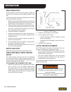
NOTE:
If the uncoupled hoses are left in the sun, pressure
increase within the hoses can make them difcult to
connect. Whenever possible, connect the free ends
of the hoses together.
TOOL RELIEF VALVE ADJUSTMENT
The relief valve on a universal pressure CT can be ad-
justed to increase or decrease the tool’s crimping force.
Standard CT’s do not have a relief valve.
The crimping tools relief valve is located below the trig-
ger guard. The relief valve on the hydraulic system is
totally separate and has a different function.
1. Perform steps 1 through 5 under Die Load Verica-
tion.
2. If the load tester indication is within the acceptable
range, the tools’ relief valve on the hydraulic system
is set correctly. If it is not, adjust the valve as follows:
a. Turn the hydraulic system control valve OFF.
b. Remove the plug from the end of the relief valve,
below the trigger guard.
c. Using a hex wrench, turn the adjusting screw.
Clockwise (CW) to increase pressure or Coun-
terclockwise (CCW) to decrease pressure.
d. Replace the plug in the relief valve and retest.
Repeat the adjustment if necessary.
TOOL OPERATION
Observe all safety precautions when operating the tool.
Read Safety and Hydraulic System Requirements, be-
fore operating the tool for the rst time.
CONDUCTOR PREPARATION
1. If the conductor is insulated, remove the insulation
from the end of the conductor.
Use an insulation stripping tool. If a stripping tool is
not available, carefully shave the insulation from the
cable.
Be sure not to nick or cut the strands of the conduc-
tor.
2. Remove any oxide or foreign matter from the ex-
posed conductor. A bright, shiny surface is required
for a good connection. Do not wire-brush tin-plated
copper conductors or tinned connectors.
3. Install the connector sleeve onto the conductor.
STARTUP
1. Clean the nibs on the tool. Remove all traces of lu-
brication from each tool nib before crimping.
2. Pull the ringed latch pin out of the latch. Rotate the
latch away from the crimping head and then place
the crimping head over the connector sleeve on the
conductor. Close the latch and reinstall the ringed
latch pin.
3. Move the hydraulic system control valve to the ON
position.
4.
WARNING
The crimping force between the dies in the tool head
can cause severe personal injury.
Keep hands away from the die area when operating
the tool.
Remove any trapped air from the tool by squeezing
the trigger 4 or 5 times to advance and retract the
piston nearly a full stroke.
5. Position the tool as follows:
a. Connector sleeves
Center the sleeve between all four nibs in the
compression head. Place the sleeve so the nibs
make the rst crimp adjacent to the center-band
mark.
Make sure the connector sleeve is carefully
centered between all four nibs in the tool.
b. H-Frame Connectors:
Place the connector in the tool so the main
groove is positioned between the top nib and ei-
ther side nib. Make sure the positioning grooves
mate with two of the nibs.
6. Squeeze the trigger to crimp the connector.