10 ► CT06 User Manual
OPERATION
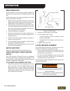
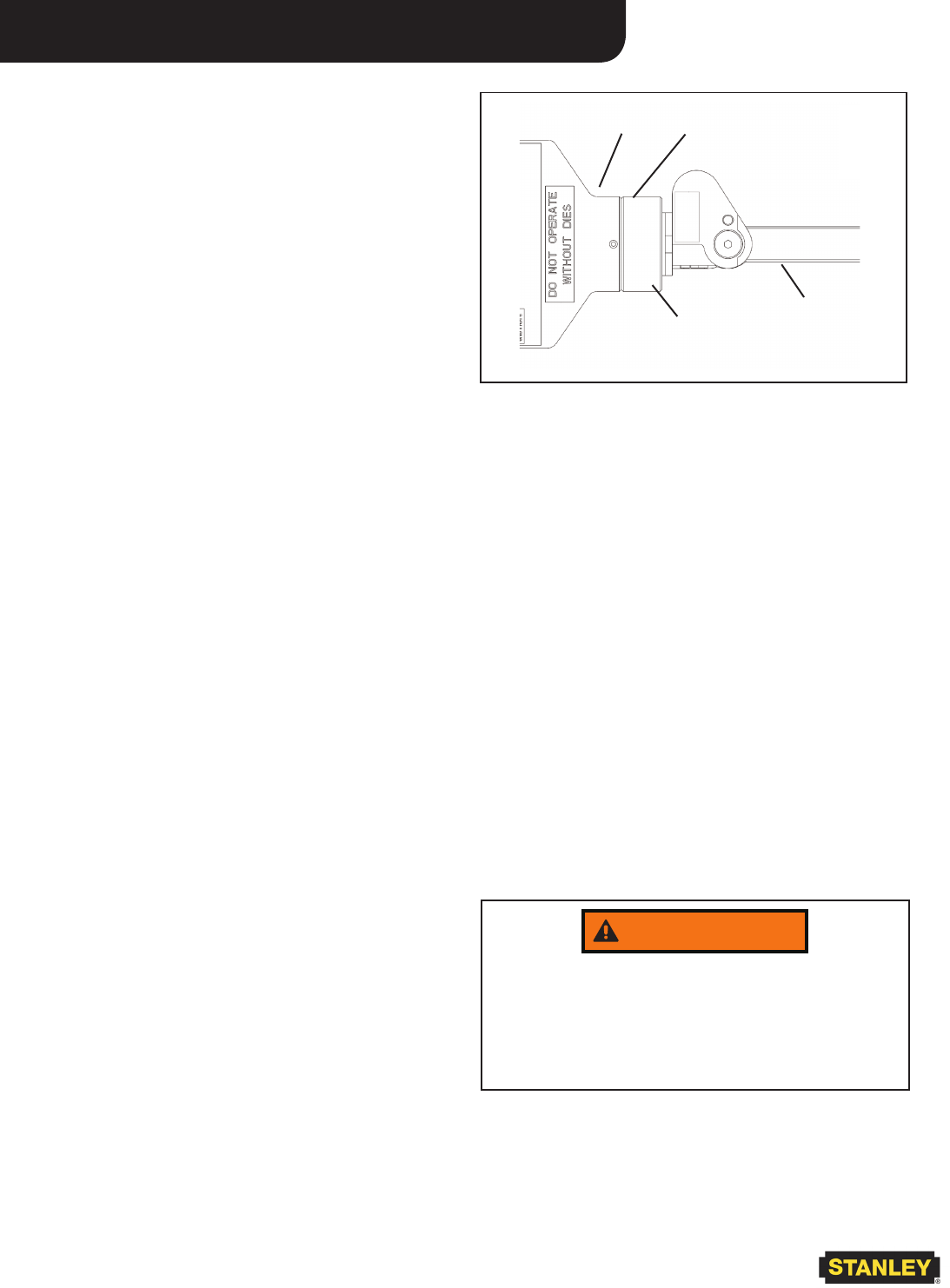
Open-Center (no gap)
Adapter
Cylinder
Trigger
Handle
Top View of Tool
Figure 2. OC/CC Setup
2. Loosen the 2 setscrews on the cylinder.
3. Turn the adapter until it stops:
• Counter clockwise (CCW) to change to closed
center (creates gap)
• Clockwise (CW) to change to open center (clos-
es gap)
4. Tighten the two setscrews.
LATCH NIB REPLACEMENT
The CT06 Hydraulic Crimping Tool has two main com-
ponents in the Anderson compression head:
• The cam yoke assembly forms the base of the com-
pression head. It functions as a movable piston die
to provide the crimping force.
• The latch assembly bridges the cam yoke across
the end of the head. The latch nib in the center of
the assembly is the stationary die.
The following procedure describes how to remove and
replace the latch nibs.
PRE-OPERATION
Careful inspection of the tool and hydraulic system be-
fore startup is important for safe, reliable operation of the
tool.
The following items should be checked daily at the start
and the end of each work shift.
1. Make sure the proper dies are securely in place. Op-
erating the tool without dies can deform the crimping
heads. Refer to Die Installation for instructions.
2. Connect hoses. Wipe all hose couplers with a clean,
lint-free cloth before making connections. Dirty cou-
plers can contaminate the hydraulic lines and pre-
vent a good seal at the connection.
3. Check all fasteners for tightness.
4. Check the equipment for oil leaks. If leaks are ob-
served, do not use the tool; have the equipment ser-
viced before use.
5. Check the tool and hydraulic system for proper op-
eration and performance.
6. If the equipment does not appear to operate prop-
erly, have it serviced before use.
7. Periodically verify the crimping force of the tool. Re-
fer to Die Load Verication.
SETUP AND TEST
Verify the crimping force before operating the tool.
OPEN CENTER/CLOSED CENTER
SETUP
The CT06 Hydraulic Crimping Tool can be congured
for either open-center or closed-center operation. The
current setting is easily determined by looking at the gap
between the adapter and the cylinder:
TO CHANGE THE CURRENT SETTING:
1. Remove the hydraulic hose coupling from the return
port on the tool, if one is installed. When making
the change from CC to OC, hydraulic uid may be
trapped in the tool, preventing complete movement
of the adapter. Remove the return coupling to allow
the hydraulic uid to escape.
WARNING
Installing dies in the tools with the hydraulic hoses
connected can cause severe personal injury or
equipment damage.
To prevent accidental start-up, always disconnect the
hoses before installing dies.


