


27.1.1999
8udh50gb_fm5.fm
4
Product: UDH-50 (Carbox) / YO0702
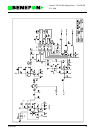
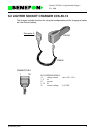
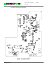
7.1.2.5 BOX V105
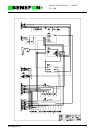
7.1.2.6 Operation
Operating voltage is fed to pin EXTVB/6. L100/C104 filters the power supply and
D100 limits any voltage peaks. When the radio telephone is placed in its handset, a
voltage is fed through the BOX/3 pin which triggers Q201 and Q200 open.
The regulator I200 feeds +9V to the audio stage and PC-connector pin 3 and I210
feeds +5V to other functions. External relay drivers Q231 and Q241 are controlled
by I2C I/O-expander I220.
The HF microphone gets its bias voltage through resistors R330 and R331. I330
serves as the microphone amplifier and as a low-pass filter with a border frequency
of 3.3 kHz.
The analog switch I320 connects the HF microphone or HS microphone signal to the
EXTMIC-line.
The analog switch I322, controlled by AUX_MODE selects either microphone (HS or
HF) or external signal source AUX_MIC to be connected to EXTMIC signal pin.
The analog switch I430 connects audio signal to handset earphone or HF-speaker.
The analog switch I431 connects audio signal to connector PC/AUX/8 or to HS erp /
HF spkr.
When audio power amplifiers I410 and I460 are not in use, they are in mute-mode.
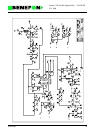
1 V_CHARGE battery charging current max. 2A / 9V
2 V_CHARGE battery charging current
3 V-BAT battery voltage
4 NC not connected
5 EXTMIC external microphone signal 400 mV RMS
6 GND ground
7 GND ground
8 EXTERP external ERP-signal 200 mV RMS
9 CADET carbox detection +5V
10 I2CINT I2C interrupt
11 SCL I2C clock
12 SDA I2C data
13 TXD RS 232
14 RXD RS 232
15 EXTIO extra-IO
16 CHGCONT
charging control from the
processor