


27.1.1999
Xo0245e4_fm5.fm
5
Product: LIF-40 (Line Interface) / YO0245
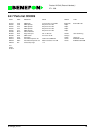
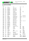
9.1.3.3 Connectors
X120
X121
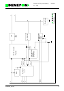
9.1.3.4 Audio
The audio unit consists of operation amplifiers I100C and I100D and their peripheral
components. The low-frequency alternating current passing through the two-wire
data terminal is formed by a current coming from the I100D output through resistor
R109 (signal received by the data terminal) and by a current coming through resistor
R109 to I100C (signal transmitted by the data terminal). R109/C111 is used for gen-
erating the line impedance appropriate to the data terminal.
The -3 dBm level (549 mVrms / 600 ohm) causes a 400 mVrms voltage in the EXT-
MIC line and a ±3 kHz deviation in the transmitter. Likewise, the ±3 kHz deviation in
the receiver causes a 400 mVrms voltage in the EXTERP line and a -16 dBm level
(123 mVrms / 600 ohm) in the data terminal.
9.1.3.5 Basic Frequencies
Components R114, R115, C109 and I105 form an oscillator vibrating at a frequency
of approx 220 kHz. This frequency is divided within I105 into frequencies 430 Hz
(free/reserved tone) and 26 Hz (ring frequency).
9.1.3.6 Switched Mode Voltage Converter
The basic chopper connection consists of operation amplifier I100A, quad NAND
I101, MOSFET Q100, and coil L100. Saw wave to the I101A input pin 2 is generated
from the basic frequency 220 kHz by using resistor R131 and capacitor C121. By
changing the dc-level of the saw wave, the operation amplifier I100A controls the
pulse width at gate Q100.
An extended width pulse from the basic frequency is brought to the I101A input pin 1
in order to make sure that the MOSFET is led to be momentarily non-conductive in
every cycle.
1 EXTMIC MIC input for hand-portable 400 mVrms
2 GND Signal ground
3 EXTERp ERP output from hand-portable 200 mVrms
4 VBAT NiCd battery voltage 7.2 V
5 I2CDAT I2C-connection data line 0/5 V
6 I2CCLK I2C-connection clock line 0/5 V
7 I2CINT I2C-connection interrupt 0/5 V
1 LB Two-wire connection to data terminal
2LA