


27.1.1999
4A0701GB.__1
9
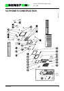
Product: TDP-52-SN3 (Sigma Gold) / OA0701 Processor
5.1.4.12 Power Adjustment
The transmitter control logic switches TX power and also adjusts it to the
correct level. The STX_REG signal sets the transmitter to ready mode. Power
is controlled by the ASIC analog output D/A 1. It is a pulse frequency
modulated output which is converted to a DC voltage by integrating it with
C379. 0V corresponds to "no power" state, and 5V to maximum transmitter
power. The power levels are calibrated by the program at the source of
measurement.
5.1.4.13 Charging Control
The charger is controlled by the program. The charger is detected by a voltage
at the SV-CHG pin. The charging current (0...1,5A) is controlled by an analog
(0...5V) CHGCONT signal which comes from the ASIC D/A 2 pulse frequency
output. Charging is governed by the battery and radio temperatures, battery
voltage, and time measurement.
5.1.4.14 Temperature Measurement
The radio has two separate temperature sensors, one within the battery pack,
and the other within the radio module. Inside the radio the NTC resistor R316
voltage is measured by the processor A/D converter. This value is converted
by a programmed table to a temperature reading.
5.1.4.15 Real-time Clock
A real-time clock is provided within ASIC to give the time and date. The alarm
function can also be programmed to the ALARM pin. This will initiate the
processor regulator and thus also the radio although it is in OFF state.
The ASIC circuit has a continuous power supply and the 32 kHz clock crystal
runs constantly. Not even the RESET line stops the clock. If the power supply
has dropped too low, the clock will need to be reset with the radio buttons (from
the menu).
5.1.4.16 Answer Module
Answer module can save a maximum 16 second message. The message can
be recorded from the microphone, external microphone or RX-audio. The
message can be sent to the earphone, external earphone or TX-audio.