


Chapter 3: Installation 9
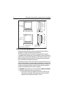
• More than 7 ft (2 m) from the path of a radar beam. A radar beam can nor-
mally be assumed to spread 20 degrees above and below the radiating
element.
• The equipment is supplied from a separate battery from that used for engine
start. Voltage drops below 10 V in the power supply to our products, and
starter motor transients, can cause the equipment to reset. This will not dam-
age the equipment, but may cause the loss of some information and may
change the operating mode.
• Raymarine specified cables are used. Cutting and rejoining these cables can
compromise EMC performance and must be avoided unless doing so is
detailed in the installation manual.
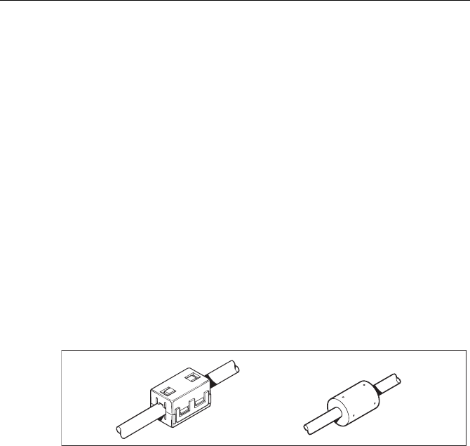
• If a suppression ferrite is attached to a cable, this ferrite should not be
removed. If the ferrite needs to be removed during installation it must be reas-
sembled in the same position.
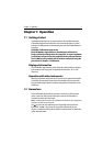
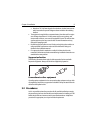
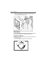
Suppression ferrites
The following illustration shows typical cable suppression ferrites used with
Raymarine equipment. Always use the ferrites supplied by Raymarine.
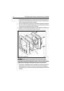
Connections to other equipment
If your Raymarine equipment is to be connected to other equipment using a cable
not supplied by Raymarine, a suppression ferrite MUST always be attached to the
cable near the Raymarine unit.
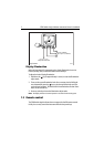
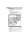
3.2 Procedures
As it is not possible to describe procedures for all possible installation scenarios,
the procedures given here describe the broad requirements for installing an ST60
Rudder Angle Indicator instrument and its associated transducer. Adapt these
procedures as appropriate, to suit your individual requirement.
D3548-6