


10 ST60 Rudder Angle Indicator Instrument Owner’s Handbook
CAUTION:
Where it is necessary to cut holes (e.g. for cable routing and
instrument mounting), ensure that these will not cause a hazard
by weakening critical parts of the vessel’s structure.
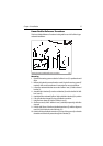
Unpacking
Unpack your ST60 instrument and check that the items detailed in the
Introduction to this handbook are present.
Each ST60 instrument is supplied with a standard bezel for surface mounting.
Optional mounting kits are available for flush mounting and bracket mounting
the instrument. If you have ordered the flush mounting option, a low-profile bezel
and four fixing screws are also provided.
Fitting the instrument
The ST60 Rudder Angle Indicator instrument can be installed using one of a
number of different mounting options:
• Surface Mounting. Gives a profile of approximately 0.95 in (24 mm).
• Flush Mounting. Gives a profile of approximately 0.25 in (6 mm)
• Bracket Mounting.
The ST60 Rudder Angle Indicator instrument can also be mounted behind a panel
with just the instrument dial and keys visible.
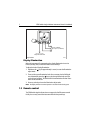
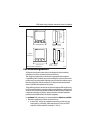
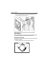
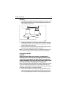
Surface mounting
To surface mount your ST60 instrument (see the
Surface mounting
illustration):
1. Ensure that:
• The selected location is clean, smooth and flat.
• There is sufficient space behind the location to accommodate the rear of
the instrument and connectors.
2. Apply the surface mount template (supplied at the rear of this handbook) to
the selected location and mark the centers for the fixing studs (1) and the
aperture (3) that will take the rear casing of the instrument.
3. Drill out the two 0.2 in (5 mm) fixing stud clearance holes (2).
4. Cut out the clearance hole (3) then remove the template.
5. Peel off the protective sheet from the self-adhesive gasket (4) then stick the
gasket into position on the rear of the instrument.
6. Screw the two fixing studs into the threaded sockets on the rear of the instru-
ment.