


Chapter 3: Installation 15
Mounting
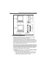
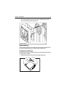
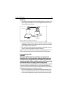
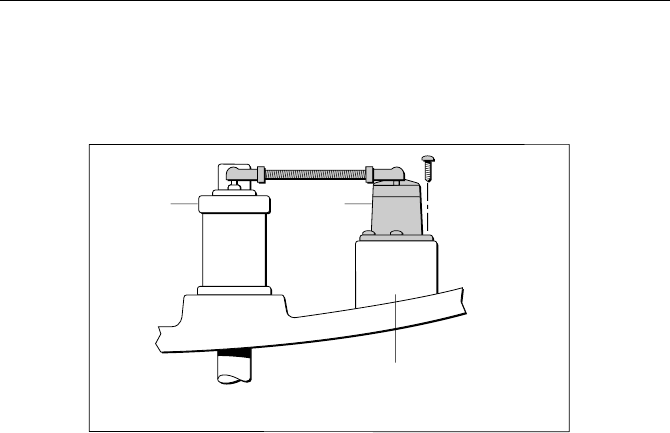
1. Ensure that the base height of the Rotary Rudder Reference Transducer is such
that it is able to maintain the correct vertical alignment between the trans-
ducer and tiller arm (as shown).
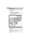
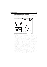
2. Using Rotary Rudder Reference Transducer template (supplied at the rear of
this handbook), mark the centers for the three securing screws at a suitable
location adjacent to the rudder stock.
3. Drill out the three 3 mm holes then, using the three self-tapping screws pro-
vided, secure the Rotary Rudder Transducer in position.
Note:
To ensure precise rudder position indication, the Rotary Rudder Reference Trans-
ducer incorporates a spring to remove any mechanical backlash in the tiller linkage.
Connecting to the tiller
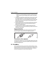
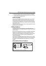
CAUTION:
The Rotary Rudder Reference Transducer arm movement is
limited to ±60°. Care must be taken during installation to make
sure that the arm is opposite the point of cable entry when the
rudder is amidships. Failure to do this could result in damage if the
arm is driven onto its end stops by the steering system.
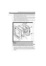
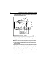
When connecting the Rotary Rudder Reference Transducer to the tiller, ensure this
is done in accordance with the limits shown in the
Rotary Rudder Reference
Transducer - as fitted
illustration (below), and that the tiller and arm of the Rotary
Rudder Reference Transducer are parallel to each other.
1. With the rudder amidships, ensure that the Rotary Rudder Reference Trans-
ducer arm is opposite the point of cable entry and at 90° to the connecting
bar. If any minor adjustment is necessary, loosen the three securing screws,
D4427-1
Vertical alignment of transducer and tiller arm
Tiller arm
Transducer
Mounting base