


18 ST60 Rudder Angle Indicator Instrument Owner’s Handbook
Note:
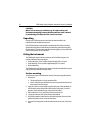
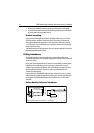
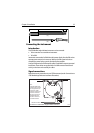
The linear feedback transducer should, under normal circumstances, be assembled
with the shaft (9) pointing to starboard. However, if it is not possible to orientate the unit in
this way, port installation is possible provided that the red and green wires are reversed at
the ST60 Rudder Angle Indicator instrument (or course computer).
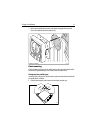
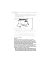
11. With the adjustment screw and barrel aligned with the spacers, close the hose
clamps (6) around the linear feedback transducer (5) and the ‘bullhorn’ ram
(1).
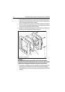
12. Tighten the ‘bullhorn’ bolt to retain the U-bracket (3).
13. Fit and tighten the nut (7) and washer (8) to the shaft of the linear feedback
transducer (5).
Transducer cabling
General
Each transducer type is supplied with sufficient cable to run from the mounted
position to either the ST60 Rudder Angle Indicator instrument (for operation as a
master) or to an autopilot (for operation as a repeater).
If you are connecting for repeater operation, use the instructions in your autopilot
handbook to connect the transducer to the autopilot.
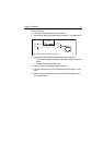
Running the cable
The manner in which you run the cable will depend on the locations of the
transducer and instrument (or autopilot). The following guidelines are provided:
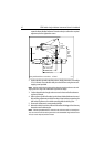
• When running cable from a Linear Rudder Reference Transducer, leave a loop
of cable at the end of the Linear Rudder Reference Transducer, sufficient to
allow for movement of the ‘bullhorn’.
• If the cable has to be fed through the deck, always use a proprietary deck
gland.
• Where cables are fed through holes, always use grommets to prevent chafing.
• Secure long cable runs so they do not present a hazard.
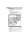
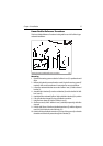
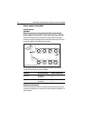
• Although the transducer cable is fitted with spade connectors for direct con-
nection to the rear of the instrument, it may be necessary to remove these to
facilitate installation e.g. if you want incorporate a junction box in the cable
run or if the cable has to be routed through narrow apertures. Extra spade
connectors are provided, to replace any that are removed when running the
cable. When fitting spade connectors, prepare the cable as at (a) in the follow-
ing illustration, then fold back the wire strands and insert into the spade con-
nector as at (b). Ensure the wire strands do not extend beyond the rear of the
spade connector insulation, then crimp the connector to the wire.