


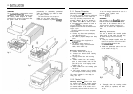
2.2 HYDRAULIC DRIVE UNIT
General guidelines
The hydraulic drive unit should be
mounted clear of spray and the possibility
of immersion in water. It should be
located as near as possible to the
hydraulic steering cylinder. It is important
to bolt the hydraulic drive unit securely to
a substantial member to avoid any
possibility of vibration that could damage
the inter-connecting pipework.
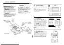
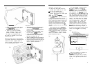
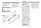
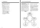
There are three basic types of hydraulic
steering system, and these are illustrated
in Fig. 15. Typical connection points for
the drive unit are shown in each case. In
all cases it is strongly recommended that
the steering gear manufacturer be
consulted.
Minimisation of hydraulic fluid loss
during connection of the drive unit will
help to reduce the time and effort
required later to bleed the system of
trapped air. Absolute cleanliness is
essential since even the smallest particle
of foreign matter could interfere with the
correct function of precision check valves
in the steering system.
Fig. 15
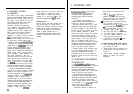
When the installation has been
completed the hydraulic pump may be
operated by switching the control unit to
Auto and operating the +
10”
and
-
10’
course change buttons. Greater motor
movements will be obtained if the rudder
control is set to maximum.
The hydraulic steering system should be
bled according to the manufacturer’s
instructions. From time to time during the
bleeding process the drive unit should be
run in both directions to clear trapped air
from the pump and inter-connecting pipe
work.
If the air is left in the system the
steering will feel spongy particularly when
the wheel is rotated to the hardover
position. Trapped air will severely impair
correct operation of the autopilot and the
steering system and must be removed.
During the installation of the system it
has not been necessary to keep track of
the connection sense to the hydraulic
steering circuit since operating sense of
the autopilot can be corrected if necessary
by reversing the pobrity of the pump drive
motor connections (see section 3.3.1).
%
T.40 Line
:
System
RESERVOIR
r(
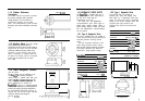
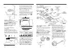
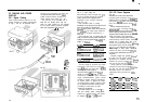
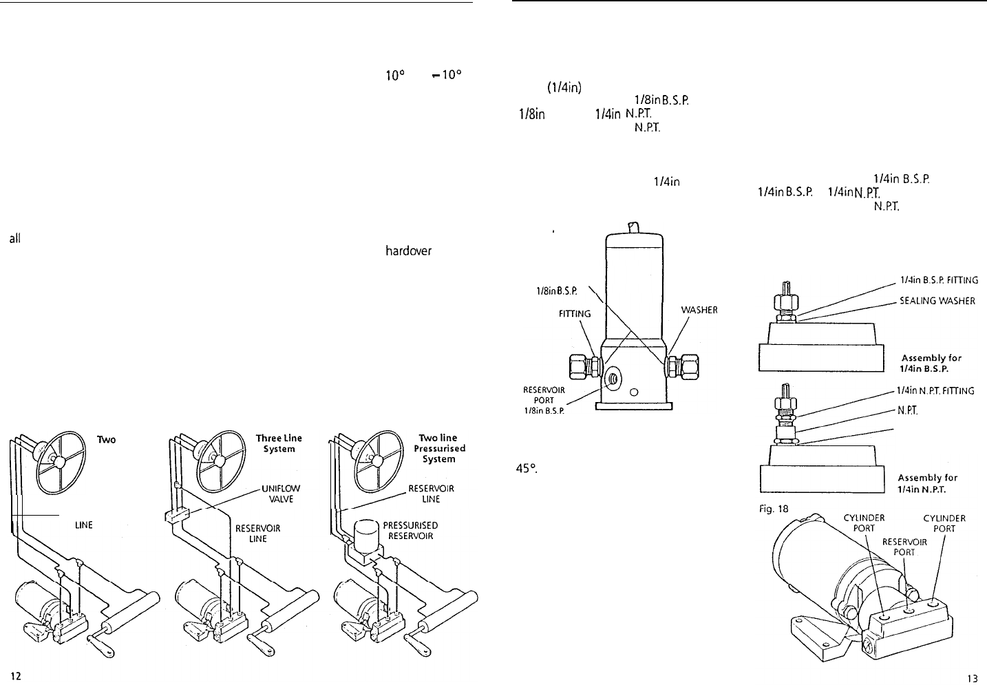
2.2.1 Type 0 Installation
The Type 0 pump must be mounted
vertically with the mounting flange bolted
to a suitable horizontal surface using four
6mm
(114in)
bolts.
All ports are tapped
1/8in
B.S.P.
Three
1/8in B.S.P. to 1/4in
N.PT.
adaptors are
included to convert to
N.PT.
where
required. The sealing washers supplied
should be placed between the fitting and
the pump (Fig. 16).
It is recommended that
1/4in
fittings or
larger are used throughout to minimise
transmission losses.
Fig. 16
’
STEERING
CYLINDER PORTS
l/h
B.S.P.
SEALING
The two cylinder ports are positioned
opposite one another on the pump body.
The reservoir port is marked R and is at
45“.
All connections to the pump should
be made with flexible hose.
Important Note
All connections in the reservoir line
must be sound as any air introduced
to this line will seriously degrade
pump performance.
Bleeding
The type 0 pump is sensitive to trapped
air, and care must be taken during
installation and commissioning to remove
it. Before connecting the hoses to the
pump:
l
Ensure all hoses are filled with oil
l
Prime the pump ports with oil
When operating the hydraulic pump to
bleed the system, turn the helm pump in
opposition. This will help any air expelled
from the hydraulic pump rise to the helm
pump reservoir.
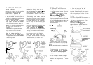
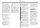
2.2.2 Type 1 Installation
The Type 1 pump should be mounted on a
suitable horizontal surface.
All ports are tapped 1/4in
B.S.P.
Three
114in
B.S.P.
to
114in
N.PT.
adaptors are
included to convert to
N.PT.
where
required (Fig. 17). The sealing washers
supplied should be placed between the
fitting and the pump (Fig. 18).
Fig. 17
l/din
N.P.T.
FirriNG
N.PT. ADAPTOR
SEALING WASHER