


l
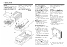
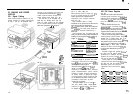
Thread the interconnect cable through
the
17mm
(518in) hole, peel off the
backing from the pads (Fig. 5).
l
Press the unit onto the mounting
surface maintaining pressure for 30
seconds to ensure a strong bond.
The control unit interconnect cable is
now ready for connection to the course
computer (See 2.3).
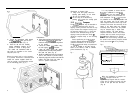
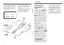
Where the control unit is to be mounted
to a painted, varnished or untreated wood
surface the carriers supplied should be
used to provide a sound bonding surface
for the
mounting
pads.
(Fig. 6).
Instructions
l Using the template supplied mark off
and drill the 17mm
(518in)
hole and
mark off and pilot drill the fixing holes
for the carriers.
l
Screw the holders
inio
position using
the self tapping screwS provided.
l
Clean the holder surface with alcohol
(oiequivalent) and stick the positive
lock pads into place (Fig. 6).
l Note An additional foam seal must be
used in this method to provide sealing.
l Carefully align the control unit with the
holders and press firmly into place to
secure a positive attachment.
Removing a Control Unit
l
Using a flat lever gently unlock the
securing pads starting at one corner.
l
Do not use excessive force.
0
The unit may be re-attached by
pressing
it’back
onto the security pads.
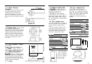
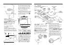
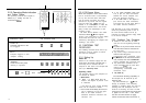
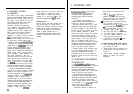
2.1.3 Fluxgate Compass
The
fluxgate
compass may be attached to
a convenient bulkhead using the self
tapping screws provided. Unscrew the top
cap to release the compass housing from
the mounting bracket (Fig. 7). Screw the
bracket to the bulkhead using the self
tapping screws provided and finally
re-
attach’the compass body to the mounting
bracket.
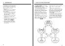
Correct positioning of the fluxgate is
crucial if ultimate performance from the
autopilot installation is to be achieved.
The
fluxgate
should ideally be positioned
as near as possible to the pitch and roll
centre of the vessel in order to minimise
gimbal disturbance (Fig. 8).
Fig. 7
Fig.
6
8
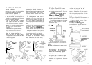
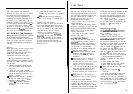
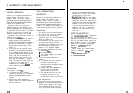
It is very important to ensure that the
fluxgate
is positioned at least 0.8m
(2ft6in)
away from the vessel’s steering
compass in order to avoid deviation of
both compasses. The
fluxgate
must also
be positioned as far away as possible from
large iron masses, such as the engine and
other magnetic devices which may cause
deviation and reduce the sensitivity of the
sensor. If any doubt exists over magnetic
suitability of the chosen site, the position
may be surveyed using a simple hand
bearing compass. The hand bearing
compass should be fixed in the chosen
position and the vessel swung through
360°. Relative differences in reading
between the hand bearing compass and
the vessel’s main steering compass should
ideally not exceed
5O
on any heading.
Fig.
8
.
0.3c to 0.5L
-I
I
.
L
+i
When the installation is complete the
fluxgate
compass should be
approximately aligned with the vessel’s
centre line by rotating the body until the
arrows on the joint line face the bows
(Fig. 9).
9