


.
I
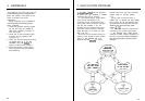
2.3 CABLING AND POWER
SUPPLIES
2.3.1 Signal Cabling
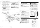
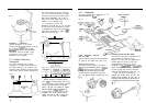
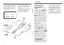
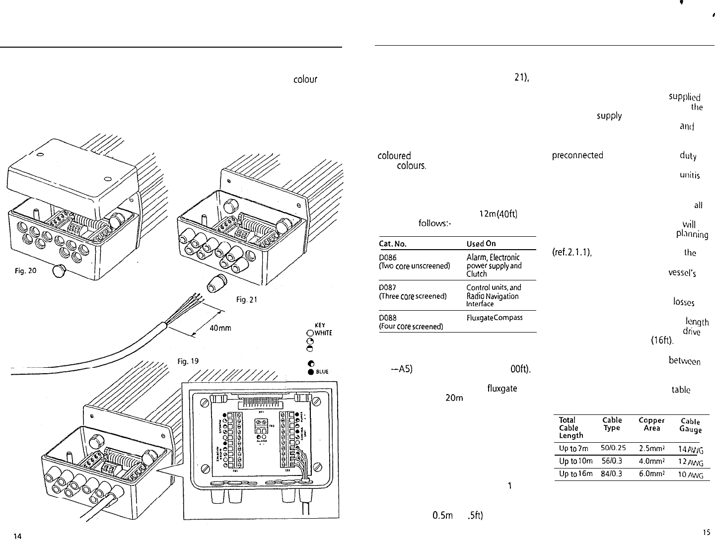
Cable interconnections between all sub
system modules are shown schematically
(in Figs 1 and 12). All peripheral units
connect to the connector unit where they
are permanently hard wired to
colour
coded connector blocks situated on a
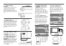
central printed circuit board (Fig. 19).
The end face of the connector unit is
fitted with ten blanking discs (Fig. 20).
which are easily pressed out and replaced
by the special rubber grommets supplied
with each peripheral unit fixing kit
_
,
_
/T
Fig.
21
-----T
40mm
KEY
0
WHlTE
0
YELLOW
0
GREEN
@RED
e
BROWN
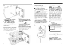
(Fig. 2 1). After cutting the
interconnecting cable to length (Fig. 21),
it may be passed through the inserted
rubber grommet and prepared for
connection to the relevant connector
block (Fig. 19).
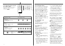
Each connector block is clearly
identified on the printed circuit board and
each wire position is identified by
coloured
dots which match the individual
wire colours. The cable screen should be
connected to terminals identified by a
white dot.
Each peripheral unit is supplied with 6m
(20ft) of interconnecting cable. Additional
cabling can be supplied in
12m
(4Oft)
cut
lengths as
follows:-
Cat. No.
Used On
DO06
(Two
core unscreened)
Alarm, Electronic
power supply and
Clutch
DO87
flhree core screened)
Control
units,
and
Radio Navigation
Interface
DO88
(Four core screened)
Fluxgate Compass
The total length of screened core cable
connected to the serial bus (connectors
Al
-A5)
should not exceed 30m (1
OOft).
Similarly, the total length of
interconnecting cable to the
fluxgate
should not exceed 2Om (60ft). If it is
necessary to exceed the above maximum
length recommendations, please consult
Nautech’s Product Support Department
for specific advice. In general the length
of interconnecting cables should be kept
to an absolute minimum to reduce the
possibility of interference by other
electronic equipment.
All cables should be run at least
1
m
(3ft) from existing cables carrying radio
frequency or pulsed signals, and should
be clamped at
0.5m
(1 .Sft) intervals.
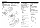
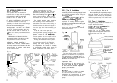
2.3.2 DC Power Supplies
(Fig. 22).
Flexible connection tails fitted with
insulated spade connectors are
SUpplicd
with the course computer to connect
ttle
main power
supply
(Blue and Brown) and
drive unit motor connections (Red
a111j
Black).
All four flexible wire tails are
preconnected to a four-way heavy duty
terminal block for connection to the main
power cabling. Similarly, the drive Ullil
iS
supplied with flexible tails for the motor
power connection (Red and Black).
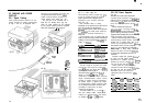
Before commencing power cabling,
all
interconnecting terminal blocks should be
screwed into a position where they
will
remain dry and protected. When pl,~nning
the position of the course computer
(ref.2.1.1).
it is important to reduce
the
overall length of heavy power cable
between the drive unit and the vessel’s
central power distribution panel to a
minimum.
Excessive lengths will generate losses in
the cable and will reduce system
performance. In addition, the cable
length
between the course computer and drive
unit must be less than 5m (16ft).
Having sited the course computer,
measure the total cable length between
the drive unit and the vessel’s central
distribution panel and select the
appropriate cable size from the table
below.
Total
Cable
Copper
Cable
Cable
Type
Area
Length
Gauge
Up to 7m
5010.25
2.5mm’
14
f’!J’srG
Up to
1
Om 5610.3
4.0mmz
12
AV’&
Up to 16m 8410.3
6.0mml
lOAWG