


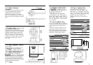
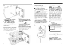
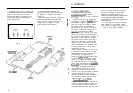

the rudder reference unit arm and tiller
Fig. 9
arm. If it is more convenient, the rudder
reference unit may be mounted upside
down (label downwards), but if this is
done, the red and green wires must be
reversed in the connector unit.
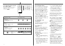
It is important to ensure that
dimensions A and B (fig. 11) are the same
at both points and that when the rudder
is amidships the unit arm is opposite the
cable gland and makes an angle of
90°
with the connecting bar.
Fig. 11
B
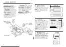
Installation Precautions
Correct installation of the course
computer and fluxgate compass is vital to
the successful performance of the
y-
I
.
r-l
Autohelm Pow&Pilot. The installation
A
I
I
A
precautions must be heeded if poor
/
performance or even failure of the
autopilot is to be avoided.
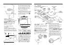
2.1.4 Rudder Reference
Transducer
The rudder reference unit must be
mounted on a suitable base adjacent to
the rudder stock (Fig. 10) using the self
tapping screws provided. The base height
must ensure correct vertical alignment of
Fig.
10
TILLER
8
e
-
400
AR,M
I
I
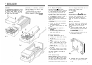
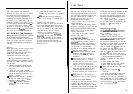
Having selected a suitable position
(Fig.
lo),
the interconnecting link A may
be cut to length and the linkage fastened
ensuring that the locking nuts B are
secure. The tiller arm should be tapped
M6 to a depth of
2Omm
(13/l 6in) or
through drilled to accept the ball joint
supplied. The rudder should then be
moved from side to side to ensure the
linkage is free from any obstruction,
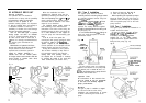
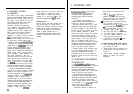
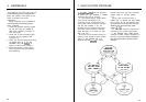
2.1.5 Accessories
The most comprehensive installation is
”
illustrated below in
Fioure
12.
RADIO NAVIGATION
INTERFACE
Fig.
12
FLUX GATE
-
CONTROL
fle
=c5
RUDDER
HYDRAULIC
DRIVE UNIT
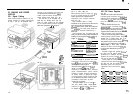
Radio Navigation Interface
(Cat. No. 2057)
This is installed using the same procedure
as given for the control unit. (See 2.1.2).
Remote Control Unit
The remote control socket is pre-wired
with the interconnecting cable. A 22mm
(7/8in) diameter hole should be bored
through the mounting panel and the
socket screwed into position using the
four self tapping screws provided (Fig. 13).
Auxiliary Alarm (Cat. No. 2035)
The auxiliary alarm unit is waterproof and
may therefore be mounted in any
position. The alarm unit is supplied with a
terminal block to connect a two core
interconnection cable to the course
computer. A 22mm
(718in)
hole
should.be
bored through the mounting panel/deck
to pass through the two way connector
block and interconnecting cable (Fig. 14).
Finally, the alarm unit should be
screwed into position using the four self
tapping screws provided. A foam seal on
the alarm mounting flange will ensure a
watertight joint to the mounting surface.
Fig. 14
11