


2.
INSTALMTION
WARNING
professionally or alternatively professional
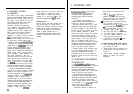
The Autohelm PowerPilot requires correct
advice be obtained if you intend to install
installation if it is to provide accurate safe
the system yourself.
self steering. Whilst designed for simple
The manufacturers can accept no
installation we strongly recommend that
liability for any claims arising from
the system should be installed
incorrect installation or product useage.
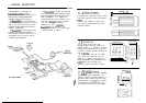
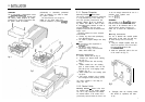
2.1.1 Course Computer
Mounting Position
-
Below Deck
The course computer should be positioned
in a dry protected area of the vessel free
from high operating temperatures and
excessive vibration.
It
can be mounted in
any attitude. Care must be taken to allow
at least
15mm
(6in) clearance all round to
aid heat dissipation from the power
amplifier in the unit. Do not mount in the
engine room.
DO NOT position the course computer
so that it will:
l
Receive any direct water splash/spray
(from Bilge/Hatch etc).
l
Be liable to physical damage from heavy
items.
0
Be covered by other equipment or
onboard gear.
l
Be close to major sources of
transmitted energy (Generators/S%
radios, Aerial Cables etc).
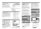
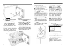
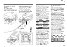
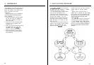
Mounting Instructions
l
Remove Terminal box lid (Fig. 2).
l
Unscrew two internal thumb retaining
nuts (Fig. 2).
l
Unplug terminal box and mounting
spine.
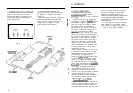
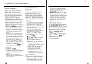
l
Position terminal box and mounting
spine in correct location, mark off and
pilot drill for the 5 self tapping screws
supplied (Fig. 3).
l
Screw terminal box and mounting spine
into place.
l
Plug course computer unit to terminal
box. Retighten thumb retaining screws.
The course computer is now ready for
wiring (see 2.3).
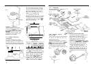
2.1.2 Control Units
Mounting Position
-
Control units must
be mounted close to the steering stations.
The unit is fully water-proof and suitable
for external location. If the control unit is
permanently exposed when the boat is not
in use we strongly recommend the use of a
protective cover (optional extra
Cat. No.
DlOl).
WARNING
Safe operation of the PowerPilot requires
that the control unit be mounted within
easy reach of the helmsman when in the
normal steering position. Position the
control unit to ensure this requirement is
met.
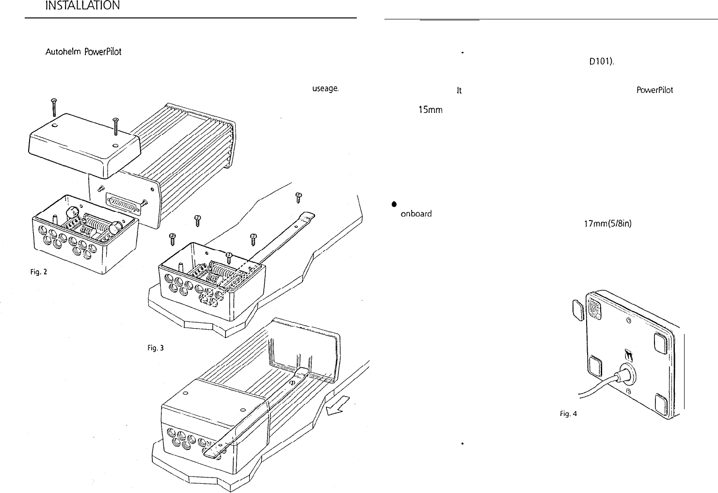
Mounting Instructions
The unit is attached with reusable positive
locking pads. In most cases, the pads may
be stuck directly onto the mounting
surface.
l
Using the template supplied, select the
control unit position, mark off and drill
the
17mm
(5/8in)
hole for the
interconnect cable.
l
Attach the positive-lock pads to the rear
of the control unit (Fig. 4).
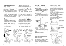
l
Thoroughly clean the mounting surface
with alcohol (or equivalent) and allow
to dry.
7