


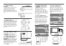
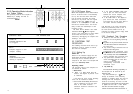


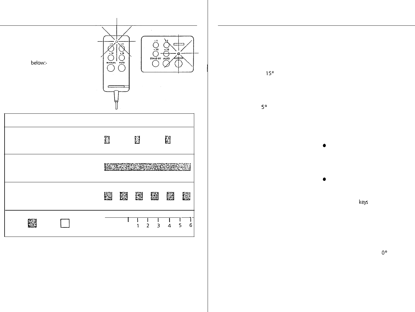
3.2.3 Operating Mode indication
and Course Display
The operating mode of the autopilot is
indicated by a flashing red LED, as
summarised below:-
OPERATING MODE
STAND BY
Autopilot switched on but
not engaged
LED FLASHING CODE
)j
y?J
f$j
AU-t-0
Autopilot engaged to steer
compass heading
MANUAL
Hand held control power
steering in operation
~~@j~fzJjj@
ii@
ON
0
OFF SECONDS
’
!
:
:
:
:
L;
20
3.2.4 Off-Course Alarm
When the autopilot is set to Auto mode a
built in off-course alarm is automatically
set up. The off-course alarm will sound
from all control units when the vessel
deviates for any reason from the original
course by more than
15“
for over 20
seconds. If an auxiliary alarm is fitted this
will also be sounded after a one minute
delay to allow the watchkeeper to take
corrective action.
The alarm will be silenced if the vessel
returns to within 1
So
of the original
course. If the vessel does not return within
course limits the alarm can only be
silenced by disengaging the autopilot and
resetting a new course.
3.3 FUNCTIONAL TEST
PROCEDURES
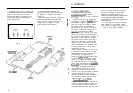
The following functional tests and set up
procedures must be carried out before
sea trials are attempted.
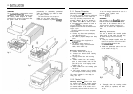
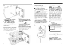
3.3.1 Setting Up
Switch On
Switch on the electrical supply from the
main panel. All control units will emit a
short beep tone to indicate that the
computer is now active. The autopilot will
start up in Stand By mode.
Operating Sense
The operating sense of the autopilot can
be checked as follows:-
* Select Auto
l
Select + 10 which should move the
rudder a few degrees to produce a turn
to starboard.
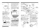
If this does not occur, correct operating
sense can be restored as follows:-
* If the rudder immediately drives hard
over to starboard, the red and green
wires of the rudder reference
transducer should be reversed in the
connector unit.
l
If the rudder immediately drives hard
over to port, the motor connections
between the course computer and
drive unit should be reversed.
l
If the rudder drives a few degrees to
port, reverse the motor connections,
and reverse the red and green wires of
the rudder reference transducer.
N.B. Reversal of the motor connections
should be permanently made at one of
the main terminal blocks and not by
reversing the spade connector flying leads
to the course computer.
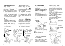
3.3.2 Functional Test Procedure
l
Switch on and note that all control
units are live and signalling Stand by
mode.
0 Key Auto on any fixed control unit and
note that Auto mode is indicated on
all control units.
l
Key course change commands from all
control units noting that
corresponding helm movements occur.
0 Key Manual on the hand held control
unit (if fitted) and note that Manual
mode is signalled from all control units.
l
Key power steer commands via the
course control keys of the hand held
control unit and note that
corresponding incremental helm
movements occur.
l
Key Stand by
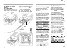
The automatic trimming capability of
the autopilot can be observed by the
following test:
Key Auto followed by a 1
O”
course
change to starboard. This effectively
simulates a condition where the need for
standing helm has developed and the
vessel is not returning to course. You will
notice that an initial fixed helm movement
is applied and that after a short interval
the drive unit will continue to apply
further incremental helm movements. If
21